Advertisement
Quick Links
Advertisement

Subscribe to Our Youtube Channel
Related Manuals for Rohm BM1Z002FJ


Summary of Contents for Rohm BM1Z002FJ
- Page 1 AC Voltage Zero Cross Detection IC BM1Z002FJ Evaluation Board...
-
Page 2: High Voltage Safety Precautions
[8] Be sure to wear insulated gloves when handling is required during operation. After Use [9] The ROHM Evaluation Board contains the circuits which store the high voltage. Since it stores the charges even after the connected power circuits are cut, please discharge the electricity after using it, and please deal with it after confirming such electric discharge. - Page 3 This evaluation board outputs a signal indicating when there is a zero voltage crossing from an input AC voltage from 90 VAC to 264 VAC. The BM1Z002FJ with the very few external components, will output a signal which is synchronous and offset in time if configured to do so, indicating when the two phases of the input AC signals are crossing 0V relative to one another.
- Page 4 (7) Confirm the output waveform ACOUT is synchronized with the AC input voltage. Caution:To avoid the electrical shock , please keep AC Power supply being isolated. Figure 2. Diagram of How to Connect © 2020 ROHM Co., Ltd. No. 62UG076E Rev.002 2/10...
- Page 5 Power supply circuit. It can be modified to span a different voltage range. Please request guidance from your local Rohm support person if a different operating voltage range is required. Power supply circuit part...
- Page 6 AC voltage zero cross delay time setting pin Ground pin Power supply pin Non connection (Do not connect to any pins.) VH_AC2 AC voltage input 2 pin VH_AC1 AC voltage input 1 pin © 2020 ROHM Co., Ltd. No. 62UG076E Rev.002 4/10 2020.07...
- Page 7 BM1Z002FJ-EVK-001 User’s Guide BM1Z002FJ・General Description - continued Important Parameter Symbo Parameter Units Conditions Input Voltage Range Output Voltage 4.75 5.00 5.25 OUTH (High Level) Output Voltage OUTL (Low Level) µs Delay Time DELAY Zero cross delay time is adjustable by the external (R3) between DSET pins and COMMON pins.
- Page 8 = 90 Vac Figure 10. Input output waveform V = 90 Vac R3:0 Ω ACOUT 5V / Div 100 V / Div Figure 11. Input output waveform V = 90 Vac © 2020 ROHM Co., Ltd. No. 62UG076E Rev.002 6/10 2020.07...
-
Page 9: Application Circuit
BM2P129T BD50FA1FP3 2.2u 220u VOUT-GND DRAIN ZNR1 100n RFN1LAM6S 220u 4.7u Non Mounted Zero cross signal circuit part BM1Z002FJ ACOUT 100k 100n ACOUT COMMON Figure 12. BM1Z002FJ-EVK-001 Application Circuit R3,R4,R5,R6,R8,Q1,PC1:Non-Mounted © 2020 ROHM Co., Ltd. No. 62UG076E Rev.002 7/10 2020.07... - Page 10 MCR18EZPJ101 Rohm 100Ω MCR18EZPJ101 Rohm Non-Mounted Non-Mounted Resistor Non-Mounted Non-Mounted 100kΩ MCR03EZPJ104 Rohm Non-Mounted Opto-coupler Non-Mounted Varistor ZNR1 Non-Mounted Black LC-2-G LC-2-G (Note 1) Materials may be changed without notifying. © 2020 ROHM Co., Ltd. No. 62UG076E Rev.002 8/10 2020.07...
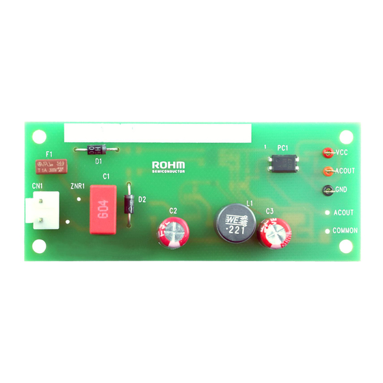
- Page 11 BM1Z002FJ-EVK-001 User’s Guide Layout Size: 36 mm x 90 mm Figure 13. TOP Silkscreen (Top view) Figure 14. Bottom Layout (Top View) © 2020 ROHM Co., Ltd. No. 62UG076E Rev.002 9/10 2020.07...
- Page 12 BM1Z002FJ-EVK-001 User’s Guide Revision History Date Rev. Changes 30.Mar.2020 New Release 13.July.2020 Figure 1, Figure 2, Figure 12, Figure 14 © 2020 ROHM Co., Ltd. No. 62UG076E Rev.002 10/10 2020.07...
- Page 13 Products. ROHM does not grant you, explicitly or implicitly, any license to use or exercise intellectual property or other rights held by ROHM or any other parties. ROHM shall have no responsibility whatsoever for any dispute arising out of the use of such technical information.
Need help?
Do you have a question about the BM1Z002FJ and is the answer not in the manual?
Questions and answers