Advertisement
Quick Links
BD18397RUV-M/BD18398RUV-M LED Drivers for Automotive Exterior Lamp.
BD18397RUV-M/BD18398RUV-M Evaluation Board
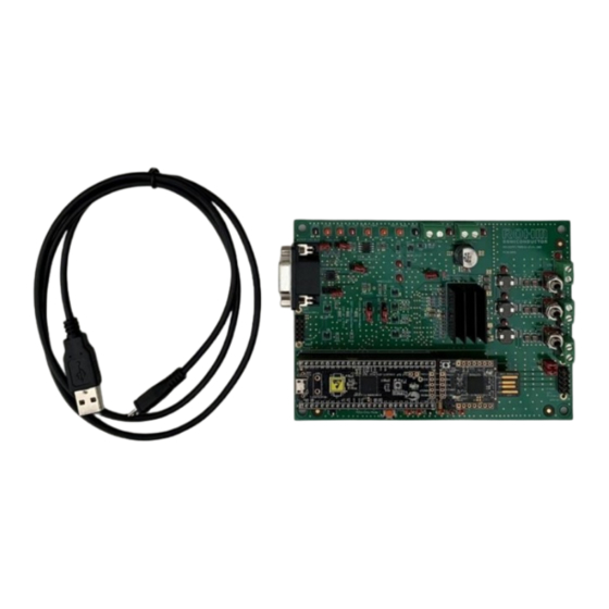
The Evaluation Kit consists of:
1.
BD18397/98RUV-EVK-302 evaluation board with BD18397RUV-M or BD18398RUV-M mounted.
2.
MCU plug-in board using CY8CKIT-059, and firmware flashed for GUI operation.
3.
For MCU only mode operation other firmware needs to be flashed into CY8CKIT-059 and is provided on request.
4.
Micro-USB cable.
© 2024 ROHM Co., Ltd.
Figure 1: BD18397/98RUV-EVK-302 Evaluation Kit
1/6
Quick Start Guide
No.
64QS001E Rev.001
July 2024
Advertisement

Subscribe to Our Youtube Channel
Related Manuals for Rohm BD18397RUV-M


Summary of Contents for Rohm BD18397RUV-M
- Page 1 BD18397RUV-M/BD18398RUV-M Evaluation Board The Evaluation Kit consists of: BD18397/98RUV-EVK-302 evaluation board with BD18397RUV-M or BD18398RUV-M mounted. MCU plug-in board using CY8CKIT-059, and firmware flashed for GUI operation. For MCU only mode operation other firmware needs to be flashed into CY8CKIT-059 and is provided on request.
- Page 2 Quick Start Guide STEP 1: Download and install the ROHM EVK GUI SW for your Windows PC/Laptop. The download link is https://www.rohm.com/support/accelerometer-evk-support. Press Download for ROHM EVK GUI SW After installation, ROHM EVK GUI appears in startup menu The CY8CKIT-059 is already flashed with the ROHM’s custom firmware (hex file).
- Page 3 Configuration of the LED Driver is performed once an internet connection is available: • Launch ROHM EVK GUI SW • In Settings select “Reconfigure product family” • In Pop-Up menu select: “ROHM EVK 3.2 for LED Drivers” Press OK © 2024 ROHM Co., Ltd.
- Page 4 CN19 is available. The header and default settings is indicated for the different connector/jumpers on the board. Below is application example with 5 LED output channels having 5 series LEDs in each channel where the BD18398RUV-M drives the 3x LED channels and the BD18397RUV-M drives the 2x channels. Figure 3: BD18397/98RUV-EVK-302 Evaluation Board set-up ©...
- Page 5 Quick Start Guide STEP 4: With the ROHM EVK GUI software installed and configured, connect the USB cable between PC/laptop and the CY8CKIT-059 plug-in board; the blue LED on CY8CKIT-059 plug-in board lights up. With the ROHM EVK GUI already launched and press “Confirm board” for example BD18398-EVK-302.
- Page 6 SW1 is located on the BD18397/98-RUV-EVK-302 Evaluation Board beside the CY8CKIT-059 plug-in board. CN16 is mounted to provide 5V supply to MCU in MCU only mode. For additional details about the BD18397/98RUV-EVK-302 Evaluation board refer to BD18397/98RUV-EVK-302 User Guide. © 2024 ROHM Co., Ltd. 64QS001E Rev.001 July 2024...
- Page 7 Specific Applications). Unless otherwise agreed in writing by ROHM in advance, ROHM shall not be in any way responsible or liable for any damages, expenses, or losses incurred by you or third parties arising from the use of ROHM Products for Specific Applications.
Need help?
Do you have a question about the BD18397RUV-M and is the answer not in the manual?
Questions and answers