Advertisement
Advertisement
Table of Contents

Subscribe to Our Youtube Channel
Related Manuals for Rohm BSMGD2G17D24-EVK001


Summary of Contents for Rohm BSMGD2G17D24-EVK001
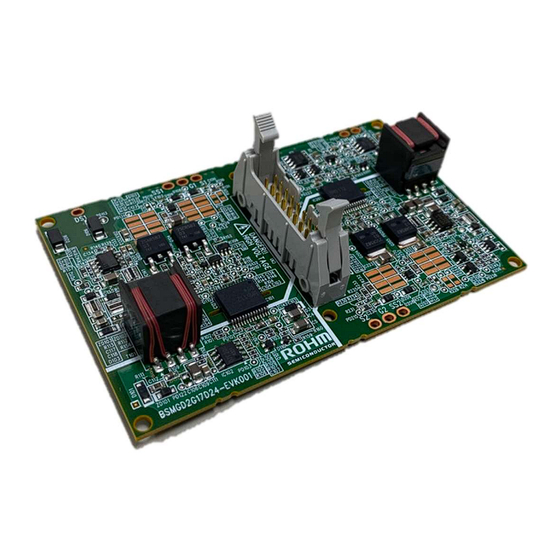
- Page 1 Evaluation Board for E-type Full SiC Module with Generation 1700V SiC-MOSFET...
-
Page 2: High Voltage Safety Precautions
[8] Be sure to wear insulated gloves when handling is required during operation. After Use [9] The ROHM Evaluation Board contains circuits which store high voltage. Since it stores charges even after turning off the connected power circuits, please discharge the electricity after using it, and please deal with it after confirming such electric discharge. -
Page 3: Precautions For Use
The evaluation board is not a final finished product suitable for use by general consumers. Therefore, please do not use the whole or a part of the evaluation board as a final finished product. www.rohm.com HVB01E © 2020 ROHM Co., Ltd. All rights reserved. - Page 4 BSMGD2G17D24-EVK001 1.Overview This evaluation board, BSMGD2G17D24-EVK001, is a gate driver board for full SiC Modules with the 2 Generation 1700V SiC-MOSFET in E type housing. This evaluation board contains all the necessary components for optimal and safety driving the SiC module.
-
Page 5: Pin Assignment
Module pin is described in Table 2, and connector CN1 pin is described in Table3. ⑯ ⑮ ⑭ ⑬ ⑫ ⑪ ⑩ ⑨ FLT-L ⑧ ⑦ PWM-L ⑥ ⑤ FLT-H ④ ③ PWM-H ② ① Figure 2. Pin assignment © 2020 ROHM Co., Ltd. No. 62UG081E Rev.002 2/30 SEP.2024... - Page 6 Table 2. Module Pin Descriptions Pin name details Drain sense (High side) Gate (High side) Source sense(High side) Gate (Low side) Source sense (Low side) Thermistor Thermistor Figure 3. MOSFET Module Pin assignment © 2020 ROHM Co., Ltd. No. 62UG081E Rev.002 3/30 SEP.2024...
- Page 7 When ENA is “H” level or open, output is disabled. 12 GND Ground 13 VCC Power Supply Voltage 14 GND Ground 15 TH Temperature monitoring output pin 16 GND Ground © 2020 ROHM Co., Ltd. No. 62UG081E Rev.002 4/30 SEP.2024...
- Page 8 ENA is pulled up by a resistor, so in case of open input, the ENA is “H”. Figure 6. ENA I/O equivalence circuits ■TH TH is output pin of the Thermistor voltage in SiC module. + - Figure 7. TH I/O equivalence circuits © 2020 ROHM Co., Ltd. No. 62UG081E Rev.002 5/30 SEP.2024...
- Page 9 The Gate drive output voltage is +19V/-4V. ■Fly-back power supply Fly-back power supply consists of ROHM’s Isolated Fly-back Converter (BD7F200EFJ) and transformer. For modification of the output voltage, please check the datasheet of BD7F200EFJ. ■Short Circuit Protection (SCP) When the Drain-Source voltage of SiC module during on state exceeds V , SCP function will be activated.
- Page 10 Module. The Thermistor Temperature vs. The output Voltage of TH is shown in Figure 9. Table 4 shows , the resistance of thermistor and the output voltage of TH for each temperature of the thermistor. The Thermistor Temperature[ ℃ ] Figure 9. The Thermistor Temperature vs. The Output Voltage of TH © 2020 ROHM Co., Ltd. No. 62UG081E Rev.002 7/30 SEP.2024...
- Page 11 ○ ○ × ON -Note H input ○:>UVP,<OVP、 ×:Don’t care Note: In case of both PWM-H and PWM-L are “H” level, SiC-MOSFET is “OFF”. (High-Side and Low-Side Simultaneous conduction prevention) © 2020 ROHM Co., Ltd. No. 62UG081E Rev.002 8/30 SEP.2024...
-
Page 12: Function Block Diagram
User’s Guide BSMGD2G17D24-EVK001 4.3 Function block diagram Function block diagram is shown in Figure 10. Driving, Logic and Protection functions are highlighted. Figure 10. Function block diagram © 2020 ROHM Co., Ltd. No. 62UG081E Rev.002 9/30 SEP.2024... -
Page 13: Specification
-5.4 Over Voltage Protection of Gate EE2OV Drive Negative bias Voltage(V Release voltage -4.7 EE2OVC Between Darin and Short Circuit detection voltage 15.2 SCDET Source Isolation Voltage 1min 3750 Vrms © 2020 ROHM Co., Ltd. No. 62UG081E Rev.002 10/30 SEP.2024... -
Page 14: How To Use
6.1.1 Peripheral circuits for gate resistors and soft turn-off resistors The SiC-MOSFET is driven by ROHM’s gate driver IC BM6112FV-C. When the SCP function is activated, the MOSFET will be turned-off slowly (soft turn-off). The turn off time is based on soft turn-off resistors. The schematics are shown in Figure 11 and Figure 14 6.1.2... - Page 15 Peripheral circuits for gate resistors and soft turn-off resistors Turn off:R124,R125 Turn on:R120,R121 R122,R123 R118,R119 Soft turn off:R126 Figure 12. The mounting position of gate resistors and soft turn-off resistors © 2020 ROHM Co., Ltd. No. 62UG081E Rev.002 12/30 SEP.2024...
- Page 16 Figure 13. Peripheral circuits for gate resistors and soft turn-off resistors Gate resistors Soft turn-off resistors NM:Not Mounted Figure 14. The mounting position of gate resistors and soft turn-off resistors © 2020 ROHM Co., Ltd. No. 62UG081E Rev.002 13/30 SEP.2024...
- Page 17 Please adjust the value of the gate resistors to not exceed the maximum rating of the drain–source voltage and the gate-source voltage at your actual application. ■Soft turn-off resistors Please adjust soft turn-off resistors to not exceed the maximum rating of the drain–source voltage at your actual application. © 2020 ROHM Co., Ltd. No. 62UG081E Rev.002 14/30 SEP.2024...
- Page 18 Input signal for CN1-7 Low side CN1-8 FLT-L Alarm(Low side) CN1-9 CN1-10 CN1-11 Enabling signal CN1-12 CN1-13 CN1-14 CN1-15 + Temperature monitor - output CN1-16 Figure 15. Recommended Interface Circuit © 2020 ROHM Co., Ltd. No. 62UG081E Rev.002 15/30 SEP.2024...
-
Page 19: Power On/Off Sequence
High. In order to output the gate signal, you need to reset the latch by supplying the High signal to ENA pin. Power On Power Off Sequence Sequence HVDC 800V to 0V (24V) (5V) (5V) (5V) (5V) HVDC 0V to 800V (24V) Figure 16. Power On/Off sequence © 2020 ROHM Co., Ltd. No. 62UG081E Rev.002 16/30 SEP.2024... - Page 20 ⑥ ⑤ FLT-H ④ ③ PWM-H ② ① NC 6 5 Figure 17. This evaluation board’s pins numbering 【SiC Module】 10 11 SiC module ’ s pins numbering Figure 18. © 2020 ROHM Co., Ltd. No. 62UG081E Rev.002 17/30 SEP.2024...
- Page 21 Note1 : Tightening torque 0.8N ・ m Note2 : Tighten diagonally ② Soldering terminal No.5 to 11 Figure 19. The assembled state of the evaluation board and SiC module © 2020 ROHM Co., Ltd. No. 62UG081E Rev.002 18/30 SEP.2024...
- Page 22 . When the SCP function is released, FLT will be set to the “L” level and the gate drive output will be SCDET enabled again. 500ns/div :300V/div :1kA/div :10V/div Figure 20. The SCP waveform(BSM250D17P2E004) © 2020 ROHM Co., Ltd. No. 62UG081E Rev.002 19/30 SEP.2024...
- Page 23 User’s Guide BSMGD2G17D24-EVK001 8. Schematics 8.1 High side Gate Drive © 2020 ROHM Co., Ltd. No. 62UG081E Rev.002 20/30 SEP.2024...
- Page 24 User’s Guide BSMGD2G17D24-EVK001 8.2 Low side Gate Drive © 2020 ROHM Co., Ltd. No. 62UG081E Rev.002 21/30 SEP.2024...
- Page 25 User’s Guide BSMGD2G17D24-EVK001 8.3 Power © 2020 ROHM Co., Ltd. No. 62UG081E Rev.002 22/30 SEP.2024...
- Page 26 User’s Guide BSMGD2G17D24-EVK001 8.4 Common © 2020 ROHM Co., Ltd. No. 62UG081E Rev.002 23/30 SEP.2024...
- Page 27 IC101,IC201,, BM6112FV-CE2 Driver IC ROHM IC102,IC202,, BD7F200EFJ-LBE2 PWM IC ROHM IC103,IC203,, S-19700A00A-E8T1U4 LDO(20V,0.4A) ABLIC *2 IC104,IC204,, BD71L4LG-1GTR Reset IC ROHM IC105,IC205,, S-19110PABH-M6T1U4 Reset IC ABLIC IC106,IC206,, BD48E30G-TR Reset IC ROHM © 2020 ROHM Co., Ltd. No. 62UG081E Rev.002 24/30 SEP.2024...
- Page 28 R130,R170,R2,R230 Resistor NON-MCR01 R270,,, Resistor R131,R231,, MCR03EZPFL3R90 3.9Ω,1%,1/10W ROHM Resistor R132,R232,, MCR10EZPF6801 6.8kΩ,1%,1/8W ROHM Resistor R133,R233,, MCR03EZPFX1003 100kΩ,1%,1/10W ROHM R134,R143,R150, Resistor MCR01MZPF4701 4.7kΩ,1%,1/16W ROHM R234,R243,R250,R4 Resistor R135,R152,R235,R252 MCR01MZPJ000 0Ω,1A ROHM © 2020 ROHM Co., Ltd. No. 62UG081E Rev.002 25/30 SEP.2024...
- Page 29 PCB assembly as well.Please inquire for PCB design, PCB fabrication, PCB assembly from Web site of Kyoden Co.,Ltd. https://www.kyoden.co.jp/rohm-sic-board/ As for 'ABLIC' products, please contact ' Kanematsu Futuretech Solutions' Because this part name is ROHM custom. mailto:Masateru_Kojima@kft.kanematsu.co.jp Please find the website of ' PROTERIAL'. https://www.proterial.com/products/soft_magnetism/isolation_transformer.html ©...
- Page 30 User’s Guide BSMGD2G17D24-EVK001 10.Layout Figure 25. Top-Layer(Top view) Figure 26. Layer 2(Top view) © 2020 ROHM Co., Ltd. No. 62UG081E Rev.002 27/30 SEP.2024...
- Page 31 User’s Guide BSMGD2G17D24-EVK001 Figure 27. Layer 3(Top view) Figure 28. Layer 4(Top view) © 2020 ROHM Co., Ltd. No. 62UG081E Rev.002 28/30 SEP.2024...
- Page 32 User’s Guide BSMGD2G17D24-EVK001 Figure 29. Layer 5(Top view) Figure 30. Bottom-Layer(Top view) © 2020 ROHM Co., Ltd. No. 62UG081E Rev.002 29/30 SEP.2024...
-
Page 33: Mechanical Dimensions
BSMGD2G17D24-EVK001 User’s Guide 11. Mechanical Dimensions Mechanical Units : mm Top View Side View Figure 31. Mechanical Dimensions © 2020 ROHM Co., Ltd. No. 62UG081E Rev.002 30/30 SEP.2024... - Page 34 Specific Applications). Unless otherwise agreed in writing by ROHM in advance, ROHM shall not be in any way responsible or liable for any damages, expenses, or losses incurred by you or third parties arising from the use of ROHM Products for Specific Applications.
Need help?
Do you have a question about the BSMGD2G17D24-EVK001 and is the answer not in the manual?
Questions and answers