Table of Contents
Advertisement
Quick Links
Advertisement
Table of Contents

Related Manuals for Rohm SENSEKIT1-EVK-101


Summary of Contents for Rohm SENSEKIT1-EVK-101
- Page 1 Sensor Evaluation Kit ROHM-SENSEKIT1-EVK-101 SENSEKIT2-EVK-101 USER MANUAL...
-
Page 2: Table Of Contents
Sensor Evaluation Kit User Manual Rev1.0 Contents 1. General Information and Introduction ..................3 1.1 Introduction .......................... 3 1.2 Quick Start Guide ......................... 3 1.3. Supported Sensor Products ....................4 2. Base Board Overview ......................... 5 2.1. Hardware ..........................5 2.2. -
Page 3: General Information And Introduction
Sensor Evaluation Kit User Manual Rev1.0 1. General Information and Introduction 1.1 Introduction The Sensor Evaluation Kit is designed to test the functional operation of various sensor types. It includes one Base Board and several Breakout Boards. The Base Board is a controller board with a LAPIS MCU. The Breakout boards are sensor boards containing different types of sensor ICs. -
Page 4: Supported Sensor Products
Sensor Evaluation Kit User Manual Rev1.0 Figure 3: Pu TTy Configuration Figure 4: Base Board Sample Output (without Breakout Board) 1.3. Supported Sensor Products Part Number Sensor Type Sensor Control Code Hall Sensor BU52011HFV Ambient Light Sensor BH1620FVC BH1721FVC UV Sensor ML8511 MEMs KMX61... -
Page 5: Base Board Overview
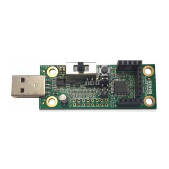
Sensor Evaluation Kit User Manual Rev1.0 Base Board Overview 2.1. Hardware The block diagram of the Base Board is shown in Figure 5. LAPIS Semiconductor's ML610Q112 MCU is used to interface with the Breakout Board via Sensor Interface Headers and with the PC via the UART-to-USB IC FT230XS-R. Figure 5: Base Board Hardware Block Diagram Figure 6: Base Board (Top View) - Page 6 Sensor Evaluation Kit User Manual Rev1.0 Designator Position Description 1 (EXT_PWR) External Power Source selected 2 (OPEN) No Power Source selected 3 (VBUS) VBUS Source selected 2-1 (USR_RST) User Reset selected 2-3 (nE_RST) nanoEASE Reset selected Table 2: Base Board - Jumper/Switch Configurations The ML610Q112 is a high-performance 8bit CMOS microcontroller that incorporates a variety of peripheral circuits, such as timers, PWM/UART/I C bus interface (master/slave), synchronous serial port, voltage level supervisor, analog comparators,...
- Page 7 Sensor Evaluation Kit User Manual Rev1.0 Figure 8: Base Board - Power Supply Schematic The debugging function of ML610Q112 is extremely useful. You will be able to single-step through your code to quickly find problems and solutions as well as set breakpoints and create and save watch lists of variables to help you better understand what is going on inside your code.
- Page 8 Sensor Evaluation Kit User Manual Rev1.0 The feedback LEDs Figure 11: Base Board - Feedback LED Schematic The UART to USB Block Figure 12: Base Board - USB to UART Schematic...
-
Page 9: Software
Sensor Evaluation Kit User Manual Rev1.0 2.2. Software The source code of the Base Board software can be downloaded from https://github.com/ROHMUSDC/ROHMSensorPlatformEVK The flow diagram of the Base Board software is shown in Figure 13. The “Sensor Control” value is the input data from the PD port of ML610Q112. -
Page 10: Breakout Board Overview
Sensor Evaluation Kit User Manual Rev1.0 Breakout Board Overview 3.1. Hall Sensor Breakout Board 3.1.1. BU52011HFV Breakout Board The BU52011HFV Breakout Board provides a simple environment to quickly evaluate the performance of the BU52011HFV sensor. The BU52011HFV features magnetic switches that can operate both the S- and N-poles, upon which the output goes from High to Low. - Page 11 Sensor Evaluation Kit User Manual Rev1.0 Figure 16: BU52011HFV Breakout Board Schematic When the BU52011HFV Breakout Board is connected to the running Base Board, • If no magnetic field is present, all LEDs will be turned off and the output text sent to the PC via UART will read: 'Hall – No Mag Fields Detected'.
-
Page 12: Ambient Light Sensor Breakout Boards
Sensor Evaluation Kit User Manual Rev1.0 3.2. Ambient Light Sensor Breakout Boards 3.2.1. BH1620FVC Breakout Board The BH1620FVC Breakout Board provides a simple environment to quickly evaluate the performance of the BH1620FVC sensor. The BH1620FVC is an analog current output ambient light sensor ideal for obtaining ambient light data for adjusting the LCD and keypad backlight in mobile phones to save power and improve visibility. - Page 13 Sensor Evaluation Kit User Manual Rev1.0 Figure 20: BH1620FVC Breakout Board Schematic Mode Install Do Not Install Illuminance Detection Range Shutdown R128, R130 R129, R131 H-Gain (default) R129, R130 R128, R131 ~1,000 M-Gain R128, R131 R129, R130 ~10,000 L-Gain R128, R131 R128, R130 ~100,00 Table 3: BH1620FVC Breakout Board - Gain Mode Configuration...
-
Page 14: Bh1721Fvc Breakout Board
Sensor Evaluation Kit User Manual Rev1.0 3.2.2. BH1721FVC Breakout Board The BH1721FVC Breakout Board provides a simple environment to quickly evaluate the performance of the BH1721FVC sensor. The BH1721FVC is a digital Ambient Light Sensor IC fwith I C bus I/F optimized for obtaining ambient light data for adjusting LCD and keypad backlighting in mobile phones. - Page 15 Sensor Evaluation Kit User Manual Rev1.0 Figure 24: BH1721FVC Breakout Board Schematic The illuminance of the ALS surface (EV) is calculated as follows: Where Raw Data refers to the 16bit serial output of the ALS. Accuracy denotes measurement accuracy (Typ. 1.2 times) The feedback LEDs display 16bit serial output of the ALS.
-
Page 16: Uv Sensor Breakout Board
Sensor Evaluation Kit User Manual Rev1.0 3.3 UV Sensor Breakout Board 3.3.1. ML8511 Breakout Board The ML8511 Breakout Board provides a simple environment to quickly evaluate performance of the ML8511 sensor. The ML8511 is a UV sensor capable of detecting the UV intensity both indoors and outdoors. An integrated amplifier converts photocurrent to voltage based on UV intensity, making it easy to connect external circuits such as an ADC. - Page 17 Sensor Evaluation Kit User Manual Rev1.0 Figure 28: ML8511 Breakout Board Schematic Designator Position Description Enable ML8511 (U59) Disable ML8511 (U59) Table 4: ML8511 Breakout Board – Jumper Positions The UV intensity of the UV sensor surface (UVI) is calculated as follows: Where V is the voltage at the output pin of ML8511.
-
Page 18: Mems Sensor Breakout Board
Sensor Evaluation Kit User Manual Rev1.0 3.4. MEMS Sensor Breakout Board 3.4.1. KMX61 Breakout Board The KMX61 Breakout Board provides a simple environment to quickly evaluate the performance of the KMX61 sensor. The KMX61 is a 6-axis e-compass device with auto-calibration software. It delivers high sensitivity (0.05 µT/count) with stability over temperature (±... - Page 19 Sensor Evaluation Kit User Manual Rev1.0 Figure 32: KMX61 Breakout Board Schematic Acceleration values (X, Y and Z) of the KMX61 are calculated using the following equations: Where: ACCEL_XOUT are the X-axis accelerometer outputs ACCEL_XOUT_L (0Ah) and ACCEL_XOUT_H (0Bh). ACCEL_YOUT are the Y-axis accelerometer outputs ACCEL_YOUT_L (0Ch) and ACCEL_YOUT_H (0Dh). ACCEL_ZOUT are the Z-axis accelerometer outputs ACCEL_ZOUT_L (0Eh) and ACCEL_ZOUT_H (0Fh).
- Page 20 Sensor Evaluation Kit User Manual Rev1.0 The magnetic values (X, Y and Z) of the KMX61 are calculated using the following equations: =MAG_XOUT×Sensitivity [μT] =MAG_YOUT×Sensitivity [μT] =MAG_ZOUT×Sensitivity [μT] Where: MAG_XOUT are the X-axis magnetometer outputs MAG _XOUT_L (12h) and MAG _XOUT_H (13h). MAG _YOUT are the Y-axis magnetometer outputs MAG _YOUT_L (14h) and MAG _YOUT_H (15h).
-
Page 21: Temperature Sensor Breakout Board
Sensor Evaluation Kit User Manual Rev1.0 3.5. Temperature Sensor Breakout Board 3.5.1. BDE0600G Breakout Board The BDE0600G Breakout Board provides a simple environment to quickly evaluate the performance of the BDE0600G sensor. The BDE0600G is a low quiescent current (16μA), high accuracy thermostat (temperature switch) IC that integrates a temperature sensor, reference voltage regulator, D/A converter, and comparator. - Page 22 Sensor Evaluation Kit User Manual Rev1.0 Figure 36: BDE0600G Breakout Board Schematic Designator Postion Detection Temperature (ºC) Open 2 - 1 2 - 3 Table 6: BDE0600G Breakout Board – Jumper Positions The temperature of the BDE0600G sensor is calculated as follows: Where V is the voltage at the output pin of BDE0600G and V is the output voltage at Temp .
-
Page 23: Appendix A: Programming The Base Board Instructions
Sensor Evaluation Kit User Manual Rev1.0 Appendix A: Programming the Base Board Instructions This appendix explains how to program the default software into the Base Board using the DTU8 Debugger. • Step 1: If the U8 Code Development tools are not installed on your PC, please install them from the CD included with the nanoEASE. - Page 24 Sensor Evaluation Kit User Manual Rev1.0 Figure 40: DTU8 Debugger Settings • Step 6: Load the default software into the Base Board by clicking on the Load Program File button and selecting the default software file. Figure 41: DTU8 Debugger - Loading Software Files Into the Base Board...
- Page 25 (such as a medical instrument, transportation equipment, aerospace machinery, nuclear-reactor controller, fuel-controller or other safety device). ROHM shall bear no responsibility in any way for use of any of the Products for the above special purposes. If a Product is intended to be used for any such special purpose, please contact a ROHM sales representative before purchasing.
- Page 26 Mouser Electronics Authorized Distributor Click to View Pricing, Inventory, Delivery & Lifecycle Information: ROHM Semiconductor SENSEKIT2-EVK-101...
Need help?
Do you have a question about the SENSEKIT1-EVK-101 and is the answer not in the manual?
Questions and answers