Table of Contents
Advertisement
Quick Links
SERVICE AND OPERATING MANUAL
PLEASE NOTE!
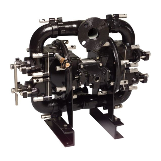
The photos shown in this manual are for general instruction only. Your
specific model may not be shown. Always refer to the parts list and explod-
ed view drawing for your specific model when installing, disassembling or
servicing your pump.
PRINCIPLE OF PUMP OPERATION
This flap swing check valve pump is powered by compressed air and is a 1:1
pressure ratio design. It alternately pressurizes the inner side of one diaphragm
chamber, while simultaneously exhausting the other inner chamber. This causes
the diaphragms, which are connected by a common rod, to move endwise. Air
pressure is applied over the entire surface of the diaphragm, while liquid is dis-
charged from the opposite side. The diaphragm operates under a balanced condi-
tion during the discharge stroke, which allows the unit to be operated at discharge
heads over 200 feet (61 meters) of water head.
Since the diaphragms are connected by a common rod, secured by plates to
the center of the diaphragms, one diaphragm performs the discharge stroke, while
the other is pulled to perform the suction stroke in the opposite chamber.
For maximum diaphragm life, keep the pump as close to the liquid being
pumped as possible. Positive suction head in excess of 10 feet of liquid (3.048
meters) may require a back pressure regulating device. This will maximize dia-
phragm life.
Alternate pressuring and exhausting of the diaphragm chamber is per-
formed by means of an externally mounted, pilot operated, four-way spool type
air distribution valve. When the spool shifts to one end of the valve body, inlet
air pressure is applied to one diaphragm chamber and the other diaphragm
chamber exhausts. When the spool shifts to the opposite end of the valve body,
the porting of chambers is reversed. The air distribution valve spool is moved by
an internal pilot valve which alternately pressurizes one side of the air distribution
valve spool, while exhausting the other side. The pilot valve is shifted at each end
of the diaphragm stroke by the diaphragm plate coming in contact with the end
of the pilot valve spool. This pushes it into position for shifting of the air distribu-
tion valve.
The chambers are manifolded together with a suction and discharge
flap-type check valve for each chamber, maintaining flow in one direction through
the pump.
INSTALLATION & START-UP
Locate the pump as close to the product being pumped as possible, keeping
suction line length and number of fittings to a minimum. Do not reduce line size.
For installations of rigid piping, short flexible sections of hose should be in-
stalled between pump and piping. This reduces vibration and strain to the piping
system. A surge suppressor is recommended to further reduce pulsation in flow.
This pump was tested at the factory prior to shipment and is ready for opera-
tion. It is completely self-priming from a dry start for suction lifts of 20 feet (6.096
meters) or less. For suction lifts exceeding 20 feet of liquid, fill the chambers with
liquid prior to priming.
AIR SUPPLY
Air supply pressures cannot exceed 125 psi (8.61 bar). Connect the pump
air inlet to an air supply of sufficient capacity and pressure required for desired
performance. When the air line is solid piping, use a short length of flexible hose
(not less than ¾" (19mm) in diameter) between pump and piping to eliminate
strain to pipes.
Warren Rupp, Inc. • A Unit of IDEX Corporation • 800 N. Main St. • Mansfield, OH 44902 USA
PULSAFEEDER ENGINEERED PRODUCTS OPERATION • 2883 Brighton-Henrietta Townline Road • Rochester, NY 14623
Phone: (419) 524-8388 • Fax: (419) 522-7867 • www.warrenrupp.com
Tel: (585) 292-8000 • Fax: (585) 424-5619 • www.pulsa.com
2" Non-Clog Wastewater
Air-Operated Double Diaphragm Pump
CE
responsibility of the purchaser to retain this
manual for reference. Failure to comply with
the recommendations stated in this manual will
damage the pump, and void factory warranty.
miscellaneous equipment must be grounded.
leakage. Follow recommended torques stated in
this manual.
piping, and all other openings and connections.
Be certain the air supply is locked out or made
non-operational, so that it cannot be started while
work is being done on the pump. Be certain that
approved eye protection and protective clothing are
worn all times in the vicinity of the pump. Failure to
follow these recommendations may result in serious
injury or death.
a product which is hazardous or toxic, the air
exhaust must be piped to an appropriate area for
safe disposition.
and must be bled of its pressure.
2" Non-Clog Wastewater Model W09
Model W09
Flap Valve Type 1
IMPORTANT
Read these safety warnings
a n d i n s t r u c t i o n s i n t h i s
manual completely, before
installation and star t-up
o f t h e p u m p . I t i s t h e
WARNING
Ta k e a c t i o n t o p r e v e n t
static sparking. Fire or ex-
plosion can result, especially
when handling flammable
liquids. The pump, piping,
valves, containers or other
CAUTION
Before pump operation, in-
spect all gasketed fasteners
for looseness caused by
gasket creep. Re-torque
loose fasteners to prevent
WARNING
Before d oing any main -
t e n a n c e o n t h e p u m p ,
be certain all pressure is
completely vented from the
pump, suction, discharge,
WARNING
In the event of diaphragm
rupture, pumped material
may enter the air end of the
pump, and be discharged into
the atmosphere. If pumping
WARNING
Before maintenance or repair,
shut off the com-pressed
air line, bleed the pressure,
and disconnect the air line
from the pump. The discharge
line may be pressurized
Page 1
Advertisement
Table of Contents

Subscribe to Our Youtube Channel
Related Manuals for Sandpiper W09


Summary of Contents for Sandpiper W09
- Page 1 Warren Rupp, Inc. • A Unit of IDEX Corporation • 800 N. Main St. • Mansfield, OH 44902 USA PULSAFEEDER ENGINEERED PRODUCTS OPERATION • 2883 Brighton-Henrietta Townline Road • Rochester, NY 14623 2" Non-Clog Wastewater Model W09 Tel: (585) 292-8000 • Fax: (585) 424-5619 • www.pulsa.com Phone: (419) 524-8388 •...
-
Page 2: Air Exhaust
This fit is important for dry priming. Once primed, the valves will function normally under dif- Figure 3: Air distribution valve ferential pressure. 2" Non-Clog Wastewater Model W09 Page 2... -
Page 3: Pilot Valve Actuator
The valve override Figure 5: Chamber vent can also be helpful when checking through the troubleshooting points mentioned elsewhere in this manual. 2" Non-Clog Wastewater Model W09 Page 3... -
Page 4: Diaphragm Replacement
Tel: (585) 292-8000 • Fax: (585) 424-5619 • www.pulsa.com Specifications are subject to improvement without notice. SANDPIPER® and Rupplon® are registered tradenames of Warren Rupp, Inc. Specifications are subject to improvement without notice Copyright © 2017 Warren Rupp, Inc. All rights reserved 2"... - Page 5 610…PTFE Encapsulated Silicon 611…PTFE Encapsulated Viton 338-005-365 Flap Valve continued next page Pilot Valve Body Assembly available in kit form. Order 031-064-000 which includes items 5,7,8 & 12. Use gasket adhesive during assembly. 2" Non-Clog Wastewater Model W09 Page 5...
- Page 6 Clean-Out Clamp Assembly 542-014-115 Stud Nut Assembly Not Shown: 535-069-000 Name Plate 705-001-330 Drive Screw 535-037-000 Caution Plate 930-009-115 Handle Wrench 031-067-010 Main Air Valve Assembly (Includes Items 9,10,11,13,14,15, 16,60) 705-001-330 Drive Screw (Cleanout Clamp) 2" Non-Clog Wastewater Model W09 Page 6...
- Page 7 Tel: (585) 292-8000 • Fax: (585) 424-5619 • www.pulsa.com Specifications are subject to improvement without notice. SANDPIPER® and Rupplon® are registered tradenames of Warren Rupp, Inc. Copyright © 2017 Warren Rupp, Inc. All rights reserved Specifications are subject to improvement without notice 2"...
- Page 8 Warren Rupp brand shall fail under normal use and service due to a defect in material or workmanship within five years from the date of shipment from Warren Rupp’s factory. Warren Rupp brands include Warren Rupp ,SANDPIPER ® ® SANDPIPER Signature Series , MARATHON , Porta-Pump , SludgeMaster™ and Tranquilizer ®...
Need help?
Do you have a question about the W09 and is the answer not in the manual?
Questions and answers