Sandpiper S20 Service & Operation Manual
Non-metallic design level 2
Hide thumbs
Also See for S20:
- Operating manual (31 pages) ,
- Service & operating manual (23 pages) ,
- Operating manual and service instructions (25 pages)
Table of Contents
Advertisement
SERVICE & OPERATING MANUAL
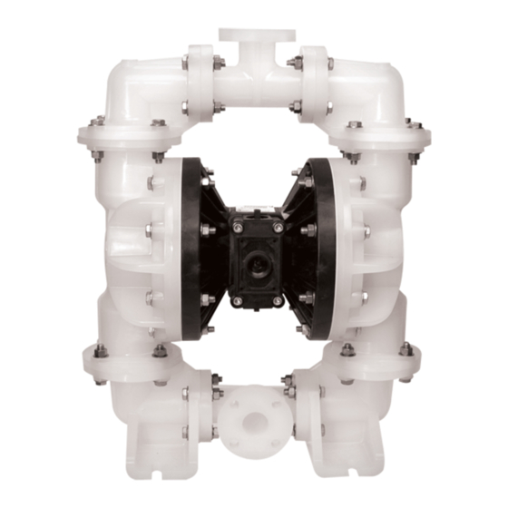
Model S20 Non-Metallic Design Level 2
Model S20 Non-Metallic Design Level 2
Model S20 Non-Metallic Design Level 2
Model S20 Non-Metallic Design Level 2
Engineering Data and Temperature Limitations ...................................................................... 1
Explanation of Pump Nomenclature ........................................................................................ 2
Performance Curve, Model S20 Non-Metallic Design Level 2 ............................................... 3
Dimensions: S20 Non-Metallic ................................................................................................. 4
Metric Dimensions: S20 Non-Metallic ...................................................................................... 5
Dimensions: S20 Non-Metallic with Spill Prevention ................................................................ 6
Metric Dimensions: S20 Non-Metallic with Spill Prevention .................................................... 7
Principle of Pump Operation .................................................................................................... 8
Installation and Start-up ........................................................................................................... 8
Air Supply ................................................................................................................................. 8
Air Valve Lubrication ................................................................................................................. 8
Air Line Moisture ...................................................................................................................... 8
Air Inlet and Priming ................................................................................................................. 8
Between Uses .......................................................................................................................... 8
Installation Guide ...................................................................................................................... 9
Important Safety Information ................................................................................................. 10
Material Codes ....................................................................................................................... 10
Troubleshooting ...................................................................................................................... 11
Warranty ................................................................................................................................. 11
Composite Repair Parts Drawing .......................................................................................... 12
Overlay Option Drawing ........................................................................................................ 12
Composite Repair Parts List .................................................................................................. 13
RuppGUARD™ Spill Prevention Option for Virgin PTFE Equipped Pumps ......................... 14
RuppGUARD™ Spill Prevention Repair Parts List ............................................................... 14
RuppGUARD™ Spill Prevention Concept ............................................................................. 15
RuppGUARD™ Spill Prevention Option Diaphragm Servicing ............................................ 15
Filling RuppGUARD™ Chambers with Liquid ....................................................................... 15
RuppGUARD™ Spill Prevention Option for TPE Equipped Pumps ..................................... 16
RuppGUARD™ Spill Prevention Repair Parts List ............................................................... 16
RuppGUARD™ Spill Prevention Concept with TPE Diaphragms ........................................ 17
RuppGUARD™ Spill Prevention Option with TPE Diaphragm ............................................. 17
Air Distribution Valve Assembly Drawing ............................................................................... 18
, INC. • A Unit of IDEX Corporation • P .O. Box 1568, Mansfield, Ohio 44901-1568 USA • Telephone (419) 524-8388 • Fax (419) 522-7867 • www.warrenrupp.com
®
520-209-000 9/03
®
Main Air Valve Assembly Parts List ....................................................................................... 18
Air Distribution Valve Servicing .............................................................................................. 19
Air Distribution Valve with Stroke Indicator Options .............................................................. 20
Air Distribution Valve with Stroke Indicator Parts List ........................................................... 20
Air Distribution Valve with Stroke Indicator Servicing ........................................................... 21
Solenoid Shifted Air Valve Drawing ........................................................................................ 22
Solenoid Shifted Air Valve Parts List ...................................................................................... 22
Solenoid Shifted Air Distribution Valve option ........................................................................ 23
Pilot Valve Assembly Drawing ................................................................................................ 24
Pilot Valve Assembly Parts List .............................................................................................. 24
Pilot Valve Servicing ............................................................................................................... 25
Diaphragm Service Drawing, Non-Overlay .......................................................................... 26
Diaphragm Service Drawing, with Overlay ........................................................................... 26
Diaphragm Servicing .............................................................................................................. 27
Overlay Diaphragm Service .................................................................................................. 27
Pumping Hazardous Liquids .................................................................................................. 28
Converting the pump for piping the exhaust air .................................................................... 28
Exhaust Conversion Drawing ................................................................................................ 28
Converted Exhaust Illustration .............................................................................................. 28
Modular Check Valve Servicing ............................................................................................. 29
Modular Check Valve Drawing ............................................................................................... 29
Dual Port Option Drawing ...................................................................................................... 30
Dual Porting Options .............................................................................................................. 31
Dual porting of both suction and discharge ends of the pump ............................................. 31
Single porting of the suction and dual porting of the pump discharge .................................. 31
Dual porting of the suction and single porting of the pump discharge ................................. 31
Leak Detection Options Drawing ........................................................................................... 32
RuppTech® Electronic Leak Detector Installation ................................................................ 32
Mechanical Leak Detector Installation .................................................................................. 32
RuppTech® Pulse Output Kit Drawing .................................................................................. 33
RuppTech® Pulse Output Kit Option ..................................................................................... 33
Exhaust Port or Auxiliary Muffler Setup ................................................................................. 33
Integral Muffler Setup ............................................................................................................. 31
CE
U.S. Patent #
400,210
5,996,627
©Copyright 2003 Warren Rupp, Inc. All rights reserved.
Advertisement
Table of Contents

Related Manuals for Sandpiper S20


Summary of Contents for Sandpiper S20
-
Page 1: Table Of Contents
Explanation of Pump Nomenclature ..................2 Air Distribution Valve with Stroke Indicator Parts List ............20 Performance Curve, Model S20 Non-Metallic Design Level 2 ..........3 Air Distribution Valve with Stroke Indicator Servicing ............21 Dimensions: S20 Non-Metallic ....................4 Solenoid Shifted Air Valve Drawing .................. -
Page 3: Engineering Data And Temperature Limitations
0°C UHMW PE 180°F -35°F 82°C -37°C For specific applications, always consult the Warren Rupp “Chemical Resistance Chart” SANDPIPER ® pumps are designed to be powered only by compressed air. 520-202-000 9/03 Model S20 Non-Metallic Design Level 2 Page 1... -
Page 4: Model S20 Non-Metallic Design Level
Explanation of Pump Nomenclature S20 Non-Metallic · Design Level 2· Ball Valve Check Diaphragm/ Check Non-Wetted Shipping Model Pump Pump Valve Design Wetted Check Valve Valve Material Porting Pump Pump Weight Brand Size Type Level Material Materials Seat Options Options... -
Page 5: Performance Curve, Model S20 Non-Metallic Design Level 2
Performance Curve, Model S20 Non-Metallic Design Level 2 (17) (34) (51) (68) (85) (102) (119) (136) (153) (127.5) (161.5) U.S. Gallons per minute Liters per minute Capacity 520-202-000 9/03 Model S20 Non-Metallic Design Level 2 Page 3... -
Page 6: Dimensions: S20 Non-Metallic
12 9/16" 18 11/16" Pulse Output Kit 4 1/16" 15 1/4" 3M Muffler Mesh Muffler 18 11/16" 12 9/16" Note: Porting Flanges are also avaible with PN10 50mm DIN bolting configuration. 520-202-000 9/03 Model S20 Non-Metallic Design Level 2 Page 4... -
Page 7: Metric Dimensions: S20 Non-Metallic
Dimension 167mm 322mm Standard Pump 357mm 202mm Pulse Output Kit 319mm 475mm 3M Muffler Mesh Muffler 380mm 225mm Note: Porting Flanges are also avaible with PN10 50mm DIN bolting configuration. 520-202-000 9/03 Model S20 Non-Metallic Design Level 2 Page 5... -
Page 8: Dimensions: S20 Non-Metallic With Spill Prevention
Pulse Output Kit 14 1/16" 7 15/16" 3M Muffler 18 11/16" 12 9/16" 14 15/16" Mesh Muffler 8 13/16" Note: Porting Flanges are also avaible with PN10 40mm DIN bolting configuration. 520-202-000 9/03 Model S20 Non-Metallic Design Level 2 Page 6... -
Page 9: Metric Dimensions: S20 Non-Metallic With Spill Prevention
RuppGUARD™ Spill Prevention Dimension 322mm 167mm Standard Pump 357mm Pulse Output Kit 202mm 319mm 475mm 225mm 380mm Mesh Note: Porting Flanges are also avaible with PN10 50mm DIN bolting configuration. 520-202-000 9/03 Model S20 Non-Metallic Design Level 2 Page 7... -
Page 10: Principle Of Pump Operation
Water in the air supply can be chamber exhausts. When the spool desired performance. When the air reduced by using a point-of-use air dryer 520-202-000 9/03 Model S20 Non-Metallic Design Level 2 Page 8... -
Page 11: Installation Guide
020-050-001 Lubricator 020-047-007 Air Dryer CAUTION The air exhaust should be piped to an area for safe disposition of the product being pumped, in the event of a diaphragm failure. 520-202-000 9/03 Model S20 Non-Metallic Design Level 2 Page 9... -
Page 12: Important Safety Information
Wear ear and eye protection. 366 ..Food Grade Nitrile RuppGUARD™, RuppTech® and SludgeMaster are registered area for safe disposition. tradenames of Warren Rupp, Inc. 520-202-000 9/03 Model S20 Non-Metallic Design Level 2 Page 10... -
Page 13: Troubleshooting
PERFORMANCE CURVE. Pump is What to Check: Blocked discharge line. cavitating the fluid by fast cycling. Corrective Action: Check for obstruction or closed discharge line valves. 520-202-000 9/03 Model S20 Non-Metallic Design Level 2 Page 11... -
Page 14: Composite Repair Parts Drawing
110/120VAC or 220/240VAC Kit 475-198-009 110/120VAC Intrinsically Safe Kit 475-198-010 220/240VAC Intrinsically Safe Kit Overlay Option Drawing RuppTech® ELECTRONIC LEAK DETECTOR KITS 032-037-000 100VAC 50Hz or 110-120VAC 50-60Hz or 220-240VAC 50-60Hz 032-045-000 12-32VDC 520-202-000 9/03 Model S20 Non-Metallic Design Level 2 Page 12... -
Page 15: Composite Repair Parts List
538-035-555 Nipple, Pipe 1" NPT Close 530-027-000 Muffler 196-148-332 Chamber, Inner 196-150-520 Chamber, Outer 196-150-552 Chamber, Outer NOT SHOWN: 286-074-354 Diaphragm 535-069-000 Nameplate 286-075-600 Diaphragm, Overlay 312-102-520 Elbow 312-102-552 Elbow 520-202-000 9/03 Model S20 Non-Metallic Design Level 2 Page 13... -
Page 16: Ruppguard™ Spill Prevention Option For Virgin Ptfe Equipped Pumps
Note: The diaphragms are to be installed with the concave side facing toward the outer chambers. See drawing. Flat side of spill prevention chamber (item 47), to face outer chamber (item 17) 520-202-000 9/03 Model S20 Non-Metallic Design Level 2 Page 14... -
Page 17: Ruppguard™ Spill Prevention Concept
Loosen the is installed in the top end cap, fill the the natural concave curve toward the pipe plug (item 52) allowing the fluid to left spill containment chamber. If the 520-202-000 9/03 Model S20 Non-Metallic Design Level 2 Page 15... -
Page 18: Ruppguard™ Spill Prevention Option For Tpe Equipped Pumps
Note: The diaphragms are to be installed with the concave toward the side facing toward the outer chambers. See drawing. outer chambers. Flat side of spill prevention chamber (item 47), to face outer chamber (item 17) 520-202-000 9/03 Model S20 Non-Metallic Design Level 2 Page 16... -
Page 19: Ruppguard™ Spill Prevention Concept With Tpe Diaphragms
If the concave curve toward the outer chamber safety clip is installed on the bottom end 520-202-000 9/03 Model S20 Non-Metallic Design Level 2 Page 17... -
Page 20: Main Air Valve Assembly Parts List
1-D, 1-F & 1-J) For pumps with alternate Mesh or Sound Dampening mufflers or piped exhaust: 031-141-002 Air Valve Assembly (Includes all items used on 031-141-000 except:) 675-044-308 Ring, Retaining 520-202-000 9/03 Model S20 Non-Metallic Design Level 2 Page 18... -
Page 21: Air Distribution Valve Servicing
Connect the compressed air line to spool. Wipe spool with a soft cloth and the pump. The pump is now ready for inspect for scratches or wear. operation. 520-202-000 9/03 Model S20 Non-Metallic Design Level 2 Page 19... -
Page 22: Air Distribution Valve With Stroke Indicator Options
(includes all other items on 031-146-000 above.) For Pumps with Alternate Mesh, Sound Dampening Mufflers or Piped Exhaust: 031-147-000 Air Valve Assembly (includes all items on 031-146-000 minus 1-D, 1-F, &1-J) 520-202-000 9/03 Model S20 Non-Metallic Design Level 2 Page 20... -
Page 23: Air Distribution Valve With Stroke Indicator Servicing
Wipe spool with a soft cloth and 1) and gasket (item 24) to the pump. inspect for scratches or wear. Connect the compressed air line to the pump. The pump is now ready for operation. 520-202-000 9/03 Model S20 Non-Metallic Design Level 2 Page 21... -
Page 24: Solenoid Shifted Air Valve Drawing
(Connector not required for explosion proof coil; coil is integral with valve) 893-098-001 Solenoid Valve, NEMA 7/9, 24VDC 893-098-002 Solenoid Valve, NEMA 7/9, 24VAC/12VDC 893-098-003 Solenoid Valve, NEMA 7/9, 120VAC 893-098-004 Solenoid Valve, NEMA 7/9, 220VAC 520-202-000 9/03 Model S20 Non-Metallic Design Level 2 Page 22... -
Page 25: Solenoid Shifted Air Distribution Valve Option
SANDPIPER pump, with one exception. This option provides a way to precisely control and monitor pump speed. BEFORE INSTALLATION Before wiring the solenoid, make certain it is compatible with your system voltage. 520-202-000 9/03 Model S20 Non-Metallic Design Level 2 Page 23... -
Page 26: Pilot Valve Assembly Drawing
Pilot Valve Assembly Parts List Item Part Number Description 095-093-000 Pilot Valve Assembly 095-092-001 Body, Pilot Valve 135-033-506 Bushing 675-055-115 Ring, Spiral Retaining 770-049-175 Spacer 917-001-374 Wiper 775-033-506 Spool, Pilot 520-202-000 9/03 Model S20 Non-Metallic Design Level 2 Page 24... -
Page 27: Pilot Valve Servicing
Inspect the wipers for the plungers in to the bushings. Push cuts and/or wear. Replace any wipers the plungers in as far as they will go. as necessary. 520-202-000 9/03 Model S20 Non-Metallic Design Level 2 Page 25... -
Page 28: Diaphragm Service Drawing, Non-Overlay
Diaphragm Service Drawing, Diaphragm Service Drawing, Non-Overlay with Overlay 520-202-000 9/03 Model S20 Non-Metallic Design Level 2 Page 26... -
Page 29: Diaphragm Servicing
Fasten the outer chamber (item 17) removal and installation. protruding stud and the 1/4-20 fastener to the pump, using the capscrews (items 11 & 12), hex nuts and flat washers. 520-202-000 9/03 Model S20 Non-Metallic Design Level 2 Page 27... -
Page 30: Pumping Hazardous Liquids
EXHAUST PIPING (items 1-D and 1-F). The 1" NPT molded LEVEL threads in the air distribution valve body (item 1-B). SUCTION Piping or hose may now be installed. LINE Illustration #3 520-202-000 9/03 Model S20 Non-Metallic Design Level 2 Page 28... -
Page 31: Modular Check Valve Servicing
Replace any worn or damaged parts as necessary. 520-202-000 9/03 Model S20 Non-Metallic Design Level 2 Page 29... -
Page 32: Dual Port Option Drawing
Dual Port Option Drawing 1½" ANSI STYLE FLANGE CONNECTION FOUR ø.62 HOLES ON A ø3.88 BOLT CIRCLE 1½" ANSI STYLE FLANGE CONNECTION FOUR ø.62 HOLES ON A ø3.88 BOLT CIRCLE 520-202-000 9/03 Model S20 Non-Metallic Design Level 2 Page 30... -
Page 33: Dual Porting Options
The discharge and suction elbows Dual Porting Drawing.) can be rotated at 90° increments (see arrows and optional positioning in the Dual Porting Drawing. 520-202-000 9/03 Model S20 Non-Metallic Design Level 2 Page 31... -
Page 34: Leak Detection Options Drawing
Kit 031-023-110 To install mechanical leak detectors, remove the bottom ¼" NPT pipe plug on the visual sight tube (item 52). Insert leak detector into the ¼" pipe tee (item 56). 520-202-000 9/03 Model S20 Non-Metallic Design Level 2 Page 32... -
Page 35: Rupptech® Pulse Output Kit Drawing
See the individual kits listed on the Pump Repair Parts List for further information. Exhaust Port or Auxiliary Integral Muffler Setup Muffler Setup MUFFLER CAP PULSE OUTPUT KIT ADAPTER PLATE PULSE OUTPUT KIT 520-202-000 9/03 Model S20 Non-Metallic Design Level 2 Page 33... -
Page 36: Warren Rupp
Declaration of Conformity Warren Rupp, Inc., 800 North Main Street, Mansfield, Ohio, certifies that Air-Operated Double Diaphragm Metallic Pumps Series: HDB, HDF, S Non-Metallic, S Metallic, Containment Duty, Gas, UL, High Pressure, W, Submersible and Tranquilizers comply with the European Community Directive 98/37/EC, Safety of Machinery.
Need help?
Do you have a question about the S20 and is the answer not in the manual?
Questions and answers