
Related Manuals for Carrier Touch Pilot Junior


Summary of Contents for Carrier Touch Pilot Junior
- Page 1 C ON TRO LS MANUAL Touch Pilot Junior 30RBS (39-160) 30RQS (39-160) Original document...
-
Page 2: Table Of Contents
4.7 - Actuators ....................................8 4.8 - Terminal block connections ..............................8 5 - HOW TO USE TOUCH PILOT JUNIOR USER INTERFACE ..................9 5.1 - Touch Pilot Junior overview ..............................9 5.2 - Touch Pilot Junior menu structure ............................10 5.3 - Read the welcome screen .............................. - Page 3 9 - DIAGNOSTICS ..................................32 9.1 - Control diagnostics.................................32 9.2 - Alarms description .................................33 10 - MAINTENANCE ................................... 35 The cover photos are solely for illustration and forms no part of any offer for sale or any sale contract. The manufacturer reserves the right to change the design at any time without notice.
- Page 4 B. Compressors in circuit A are labelled A1, A2, A3, whereas compressors in circuit B are labelled B1, B2. The support of a qualified Carrier Service Engineer is strongly recommended to ensure optimal operation of the Building Management System...
-
Page 5: Safety Considerations
Carrier 30RBS chillers and 30RQS heat pumps come with hazardous if certain factors particular to the installation a Touch Pilot Junior control that serves as the user interface and configuration tool for Carrier communicating are not considered: operating pressures, electrical components, voltages, and the installation site (elevated devices. -
Page 6: Control Components
② ① ③ ④ ⑤ ⑥ ⑦ Figure 1: 30RBS unit with Touch Pilot Junior control (picture for reference only) Legend: Low sound fan system Touch Pilot Junior control system Condenser Hydronic module with variable speed pump control (option) Evaporator... -
Page 7: Hardware
4.1 - Control boards 4.5 - Pressure transducers Three types of transducers (high pressure, low pressure, All boards making up the Touch Pilot Junior control water pressure) are used to measure various pressures in system are installed inside the electrical cabinet. They communicate via an internal LEN bus. -
Page 8: Actuators
4.7 - Actuators Water heat exchanger pumps (optional) Electronic expansion valve The controller can regulate one or two fixed speed or The electronic expansion valve (EXV) is used to adjust the refrigerant flow to changes in the operating conditions of variable speed water heat exchanger pumps and takes care of the automatic changeover between these pumps (see the machine. -
Page 9: How To Use Touch Pilot Junior User Interface
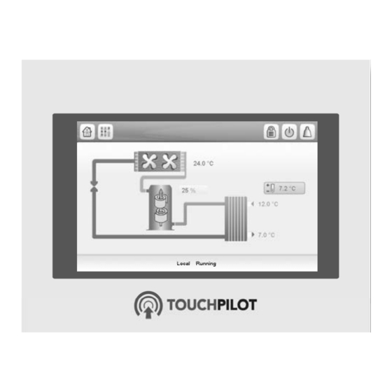
5 - HOW TO USE TOUCH PILOT JUNIOR USER INTERFACE Log in / Lo g out nit status rm display Home button rrent menu Main m menu disp play Main m menu button button rrent ifications Figure 2: Touch Pilot Junior user interface display... -
Page 10: Touch Pilot Junior Menu Structure
5.2 - Touch Pilot Junior menu structure... -
Page 11: Read The Welcome Screen
5.3 - Read the welcome screen The bell located in the upper-right part of the screen lights when any fault is detected. The Welcome screen is the first screen shown after starting the user interface. It displays the application name as well By default, the parameters are presented in metric units. -
Page 12: Set The Schedule
5.7 - Set the schedule 5.8.1 - Security access settings The control incorporates two time schedules, where the User-level security ensures that only authorised users are first one (OCCPC01S) is used for controlling the unit start/ allowed to modify critical unit parameters. stop, whereas the second one (OCCPC02S) is used for controlling the dual setpoint. -
Page 13: Monitor Unit Parameters
The Main menu provides access to the main control Display language can be modified in the User Login parameters, including general parameters, inputs and Screen on the Touch Pilot Junior user interface. outputs status, etc. To change a display language:... -
Page 14: Modify Unit Parameters
5.11 - Override system configuration General unit parameters The General parameters screen provides access to a set of In some cases it is possible to override system general unit parameters. configuration. The override screen provides the option to To access the General parameters screen, go to the Main issue the command overriding the current operation of the unit. -
Page 15: Web Connection
6.1 - Web interface 6.3 - Manage web browser settings Minimum web browser configuration: The Touch Pilot Junior control can be accessed via a web • Internet Explorer (version 8 or higher) or Mozilla browser (Internet Explorer, Mozilla Firefox, etc.). -
Page 16: Setting Up Touch Pilot Junior - Parameters
7 - SETTING UP TOUCH PILOT JUNIOR - PARAMETERS 7.1 - Main menu Icon Displayed text* Description Name General Parameters General parameters GENUNIT Temperature Temperatures TEMP Pressure Pressures PRESSURE Inputs Inputs status INPUTS Outputs Outputs status OUTPUTS Pump Status Pump status... - Page 17 Temperature Menu – TEMP Status Unit Displayed text* Description Point name °C / °F Entering Water Temp Entering water temperature: Used for capacity control °C / °F Leaving Water Temp Leaving water temperature: Used for capacity control °C / °F External Temperature Outdoor air temperature: Used to determine a number of control mechanisms such as heat/cool changeover, water exchanger...
- Page 18 Outputs Menu – OUTPUTS Point name Status Unit Displayed text* Description off/on CP_A1 Compressor A1 Output Compressor A1 status off/on CP_A2 Compressor A2 Output Compressor A2 status off/on CP_A3 Compressor A3 Output Compressor A3 status off/on FAN_A1LS Fan A1LS Output Fan A1 low speed status off/on FAN_A1HS...
- Page 19 Runtime Menu – RUNTIME Point name Status Unit Displayed text* Description hr_mach hour Machine Operating Hours Unit operating hours st_mach Machine Starts Number Number of unit starts hr_cp_a1 hour Compressor A1 Hours Operating hours, compressor A1 st_cp_a1 Compressor A1 Starts Number of starts, compressor A1 hr_cp_a2 hour...
-
Page 20: Configuration Menu (Config)
Setpoint Menu – SETPOINT Point name Status Default Unit Displayed text* Description csp1 -28.9 to 20.0 °C Cooling Setpoint 1 Cooling setpoint 1 -20.0 to 68.0 44.6 °F csp2 -28.9 to 20.0 °C Cooling Setpoint 2 Cooling setpoint 2 -20.0 to 68.0 44.6 °F hsp1... - Page 21 General Config Menu – GENCONF Point name Status Default Unit Displayed text* Description lead_cir 0 to 2 Cir Priority Sequence Circuit priority sequence 0=Auto 1=A Lead 2=B Lead 0 = Automatic changeover 1 = Circuit A lead 2 = Circuit B lead seq_typ no/yes Staged Loading Sequence...
- Page 22 Point name Status Default Unit Displayed text* Description I_cr_no 0 to 20 Current No Reset Value Current no reset value I_cr_fu 0 to 20 Current Full Reset Value Current full reset value cr_deg -16.7 to 16.7 Cooling Reset Deg. Value Cooling reset deg.
-
Page 23: Alarm Menu
Date/Time Menu – DATETIME Point name Status Default Unit Displayed text* Description Date (DD/MM/YY) d_of_m 1 to 31 Day of month Day of the month month 1 to 12 Month of year Month year 0 to 99 Year Year Monday-Sunday Day of Week Day of the week Time (HH:MM) -
Page 24: Standard Control Operations And Options
8 - STANDARD CONTROL OPERATIONS AND OPTIONS • Start/stop force command [CHIL_S_S]: Chiller start/ 8.1 - Unit start/stop control stop force command can be used to control the chiller state in the Network mode. The unit state is determined based on a number of factors, including its operating type, active overrides, open Command set to stop: The unit is halted. -
Page 25: Heating/Cooling/Standby
8.2 - Heating/Cooling/Standby When Cooling mode is selected, the unit will operate in The control determines the heat/cool state of the unit. Chillers fitted with a boiler may operate in cooling or the Cooling mode and, as a result, the boiler or electric heating mode. -
Page 26: Cooling/Heating Selection
8.3 - Cooling/heating selection 8.4.1 - Boiler control Boiler is activated when the outside air temperature is below the user-configured boiler outdoor temperature Cooling/Heating selection applies to chillers with the threshold which is by default set to -10°C (14°F). boiler and heat pumps. Cooling/Heating selection can be controlled in various ways, depending on the active operating type. -
Page 27: Hydronic Kit Option
IMPORTANT: Pump speed configuration can be on even days and the second pump is started on odd days. performed only by Carrier service. Starting the pump periodically for a few seconds extends the lifetime of the pump bearings and the tightness of the 8.5.2 - Pumps configuration... -
Page 28: Control Point
8.7 - Control point 8.7.1 - Active setpoint Two setpoints can be selected, where the first setpoint is The control point represents the water temperature that used during occupied periods, whereas the second one is the unit must produce. The required capacity can be used during unoccupied periods. -
Page 29: Capacity Limitation
(value weighted by their operating time). 8.8 - Capacity limitation 8.9.1 - Circuit loading sequence Touch Pilot Junior allows for the constant control of the This function determines in which order the circuit unit capacity by setting its maximum allowable capacity. -
Page 30: Free Cooling Option
To set the circuit loading sequence Navigate to the Configuration menu. fc_oat: Free Cooling OAT Select General Config (GENCONF). fc_wloop: Free Cooling Water Temperature fc_start: Free Cooling Start Threshold (service access only) Set Staged Loading Sequence [seq_typ]. Note: [fc_wloop] and [fc_oat] temperatures measured by Staged loading sequence [seq_typ] the control are read-only values that can be verified in No/Yes... -
Page 31: Coil Pressure Control
If the master unit is stopped due to an alarm, the slave unit is authorised to start. IMPORTANT: Master/slave assembly can be configured only by Carrier service. -
Page 32: Diagnostics
Alarm history menu. Touch Pilot Junior gives quick access to monitor all unit To access alarms history operating conditions. If an operating fault is detected, the... -
Page 33: Alarms Description
9.2 - Alarms description 9.2.1 - Alarms Name Code Description Reset Action taken Possible cause COOL_EWT_F 15001 Water Exchanger Entering Fluid Automatic, if thermistor Unit shuts down Defective thermistor Thermistor Failure reading returns to normal COOL_LWT_F 15002 Water Exchanger Leaving Fluid Thermistor As above As above As above... - Page 34 Water Exchanger Temperature Sensors Manual Unit shuts down Input and output Swapped temperature reversed SERVICE_ 130-nn Service maintenance alert Manual None: Contact Carrier Servicing required MAINTNANCE_ service ALERT DRV_FAN_A_F 16001 Circuit A Variable Speed Fan Failure Automatic Circuit A shuts down...
-
Page 35: Maintenance
Carrier qualified personnel, the optimal tool to manage your Maintenance Contract with your local Carrier Service Agency. - Page 36 Order No. 10099, 02.2016. Supersedes order No.: 10099, 08.2015. Manufacturer: Carrier SCS, Montluel, France. Manufacturer reserves the right to change any product specifications without notice. Printed in the European Union.
Need help?
Do you have a question about the Touch Pilot Junior and is the answer not in the manual?
Questions and answers