
Related Manuals for Pavone Systems MCT 1302


Summary of Contents for Pavone Systems MCT 1302
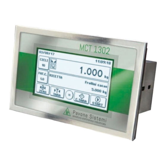
- Page 1 TECHNICAL MANUAL MCT 1302 Touch screen batching version with RS232 serial, analog and Fieldbus Software version PW1507 output PAVONESYSTEMS...
- Page 2 Page II...
-
Page 3: Table Of Contents
TABLE OF CONTENTS PRECAUTIONS ....................Page INTRODUCTION ................... Page TECHNICAL FEATURES ................... Page INSTALLATION ....................Page FRONT PANEL OF THE INSTRUMENT .............. Page 16 MAIN SCREEN ....................Page 17 INFO DISPLAY ....................Page 19 OPERATING FUNCTIONS ................Page 20 BATCHING RECIPES SELECTION ..............Page 22 MENU STRUCTURE .................. -
Page 4: Precautions
PRECAUTIONS READ THIS MANUAL BEFORE using or servicing the instrument. FOLLOW these instructions carefully. KEEP this manual for future use. CAUTION The purpose of this manual is to make the operator aware of the texts and explanatory figures, the basic requirements and criteria for the installation and correct use of the instrument. -
Page 5: Introduction
2 tensioning screws supplied. The MCT 1302 uses the RS232 serial port with ASCII protocols, to be connected to the PC, PLC and re- mote units with a maximum distance of 15m beyond which it is necessary to use the RS422/RS485 serial output that allows the connection also with MODBUS RTU protocol up to 32 addressable instruments. - Page 6 IDENTIFICATION PLATE OF THE INSTRUMENT It is important to communicate this data, in case of request for information or indications concerning the instrument, together with the program and version number, shown on the cover of the manual and displayed when the instrument is switched on. PAVONE SISTEMI WARNINGS The procedures listed below must be performed by specialized personnel.
-
Page 7: Technical Features
TECHNICAL FEATURES Power supply 18÷30 Vdc Max. absorption Isolation Class II Installation category Cat. II Working temperature -10°C ÷ +50°C (Max. humidity 85% without condensation) Storage temperature -20°C ÷ +70°C Display Graphic 240x128 pixel LCD Keyboard 4 wire resistive touch screen Overall dimensions 150 x 95 x 26 mm (l x h x w) including terminal blocks... -
Page 8: Installation
2 tensioning screws supplied. Rmax 2 138±1 The MCT 1302 must not be immersed in water, subjected to jets of water and cleaned or washed with solvents. Do not expose to heat or direct sunlight. Do not install the instrument near power equipment (motors, inverters, contactors, etc.) or near devices that do not comply with CE regulations for electromagnetic compatibility. - Page 9 MCT S 1302 DIMENSIONS Page 7...
- Page 10 ELECTRICAL INSTALLATION The MCT 1302 instrument uses for the electrical connection of the 3.81 mm removable screw terminal blocks. The load cell cable must be shielded and channeled away from power cables to avoid elec- tromagnetic interference. The field wiring of the instrument must be suitable for the environment in which it will be used and must comply with all national regulations.
- Page 11 7 +Exc. -Sig 8 -Exc 9 Shield In case of use of two or more load cells, use appropriate junction boxes (CEM4/C or CSG4/C) of which the connection is shown below. J-BOX CGS4 MCT 1302 +EXC +ALM -SGN -SIG1 -EXC -ALM...
- Page 12 LOGIC INPUTS The logic inputs are insulated from the instrument through optocouplers. The connection cables of the logic inputs must not be channeled with power cables. Use a shorter connection cable as possible. To activate a logic input, it must be brought to the positive of a 24Vdc power supply while the common item must be connected to its negative.
- Page 13 If the cable has more conductors than those used, connect the free wires to the screen. The serial connection cable must have a maximum length of 100 meters. The cable must not be channeled with other cables, but must possibly follow its own path MCT 1302 20 S I/O+ External...
- Page 14 The cable must not be channeled with other cables (i.e. outputs connected to contactors or power ca- bles), but must possibly follow its own path. The PC used for the connection must comply with the EN 60950 standard. NOTE: If there is a fieldbus, the RS485 is not available. MCT 1302 TX+/RX+ 15 TX+/RX+ TX-/RX-...
- Page 15 USB DEVICE (SPECIFICATION 2.0 COMPLIANT, FULL-SPEED 12 MBPS) Use this communication port to directly interface a PC via a USB port. Use a standard USB cable for the connection. To connect the instrument via the USB device port, the appropriate driver for the operating system used must be installed on the PC.
- Page 16 By putting several MCT 1302 instruments in series, the MASTER will be connected to the IN connector of the first MCT 1302 whose OUT connector will connect to the IN connector of the next, etc. Refer to the previous page for connection notes and warnings.
- Page 17 For reliable operation of the fieldbus, a line terminator should be used at both ends. In case of multiple MCT 1302 instruments, use the line end only on an instrument. For the setup of the board, the GSD file (hms_1810.gsd) is available and must be installed in the master.
-
Page 18: Front Panel Of The Instrument
FRONT PANEL OF THE INSTRUMENT The MCT 1302 is a touch screen instrument dedicated to batching applications. The main operating characteristics are: • Programmable recipes, standard - 100 recipes of 20 steps. With Alibi memory option - 1000 recipes with 20 steps. -
Page 19: Main Screen
MAIN SCREEN From this screen it is possible to access all the operational and programming functions of the instrument, following the indicated commands. Date Time Batching cycles Weight quadrant Recipe Recipe correction quadrant factor F1 Operation key F4 Operation key F3 Operation key Menu key F2 Operation key... - Page 20 OPERATION KEYS Access to the parameter programming menu. Press in the weight display dial to switch the weight display (net, gross). Access to the recipe selection screen. Press in the setting screen for the number of batching cycles. Access to the recipe correction factor setting screen. The correction value change creates the printout of the recipe with the recalculated batching set point.
-
Page 21: Info Display
INFO DISPLAY ERROR INDICATIONS AND MESSAGES OF WEIGHT Weight calibration not performed; flashing message, alternating with the display of the detected weight. Indication displayed when the instrument is switched on, while waiting for the conditions necessary for automatic zeroing of the weight;... -
Page 22: Operating Functions
OPERATING FUNCTIONS SWITCHING THE GROSS/NET WEIGHT DISPLAY Press on the weight dial on the instrument main screen to switch the weight display. Each time the di- splayed weight changes between the following values: • Gross - the gross weight is displayed in the weight dial. • Net - the net weight is displayed in the weight dial. - Page 23 PRINT This operation allows to print the weight. (if the printer protocol is selected, the shown recipe is prepared). This operation is always executable; the conditions necessary for totalizing the weight are not checked. 12/11/2015 10:30 OPERATOR ID GROSS WEIGHT 211.5 kg TARE 2.5 kg...
-
Page 24: Batching Recipes Selection
RECIPE BATCHING SELECTION Press on the recipe dial, in the instrument main screen, to access the active recipe selection screen. The available recipes are displayed, divided into pages of 4 elements. Press on the recipe line you want to activate. To quickly select an item in the archive, hold down the page change key for a long time, and the recipe index setting screen will be displayed. - Page 25 BATCHING Press the START operation button to start the batching, so the following screen is displayed: Indication of batched weight and setpoint Indications of the recipe status Batching reports Operation key F1 Operation key F4 Operation key F3 Operation key F2 OPERATION KEYS Batching stop command.
- Page 26 TECHNICAL NOTES REGARDING BATCHING • At the beginning of the batching, different compatibility checks are performed between the selected recipe and the system conditions. Any errors are promptly selected. • In the case of Coarse and Fine batching, the slow-down set point is so determined: SET - PRESET - Inflight.
- Page 27 Restart phase after a blackout; the instrument is waiting to receive the RESTART batching restart command or the suspended batching stop command. UNLOADING Unloading phase in progress (set unloading or total unloading). Recipe error not selected; this condition is checked during the start of the RECIPE NOT SELECTED batching.
-
Page 28: Menu Structure
• In case of product dosed out of tolerance, an asterisk is printed. • The indicated set corresponds to the actual set multiplied by the possible correction factor. MENU STRUCTURE The menu screens are subdivided into two types: command menu and parameter menu, depending on the context and structure of the data programming menus. -
Page 29: User Menu
Exit button from the menu (the top-level menu or the base screen is displayed. USER MENU USER MENU (COMMANDS) MESSAGE DESCRIPTION ACT./REC. ARCHIVE Programming menu of activities and recipes. Menu for viewing and managing totals, divided by activity and ACT./REC. TOTALS recipes. - Page 30 ENTER AND EDIT ACTIVITY Fieldbus Message Description Type Units Default Range address Max. 14 0252- Alphanumeric name of the activity. alphanumeric 0258 characters [0] AUTO DOS. [1] MAN. DOS. [2] TOT. UNL. [3] INT. UNL Selection of the activity type. (*) [4] SET ACT.
- Page 31 The set tolerance value is checked at the end of the batching. If the net weight batched does not fall within the range determined by set + tolerance and set - tolerance, an 0264 error message will be displayed (MSW) until the alarm is manually silenced.
- Page 32 This parameter allows you to set the Fine output associated with this activity (the same output can be shared by several activities). By programming this parameter to 0÷32 0269 zero, no fast output is associated with the activity. Parameter used in case of "activity type”...
- Page 33 • Intermediate unloading: Unloading to set; the amount of weight to be unloaded is programmed in the recipe. • Waiting for confirmation: Manual confirmation activity; to continue with the next recipe step, the operator must press the confirmation key or close the selected input. • Timer: Waiting step;...
- Page 34 ENTER/EDIT RECIPE (parameters, commands) Fieldbus Message Description Type Units Default Range address Max. 14 Recipe Alphanumeric name of the Alphanumeric 0202- alphanumeric name recipe. setup 0208 characters Numeric Step no. Number of recipe steps (*) 0 - 20 0209 setup RECIPE It accesses the recipe SETUP...
- Page 35 DELETE RECIPE The recipes stored in the archive are displayed, divided into pages of 4 elements. Press on the recipe line that you wish to delete; the confirma- tion of the deletion operation is always requested. To activate fast selection, long-press the page change key.
- Page 36 OPERATION KEYS It deletes the activity/recipe total displayed. Totals print function. EXAMPLE OF TOTAL PRINT 03/08/17 11:09 ACTIVITY TOTAL Sugar 230,587 kg Cacao 750,879 kg Flour 00 826,742 kg Salt 326,820 kg TOTAL 2135.028 kg AMOUNT • Only non-zero totals are printed. • The identification code of the instrument is printed (“Address”...
-
Page 37: Batching Parameters Menu
BATCHING PARAMETERS MENU BATCHING PARAMETERS Fieldbus Message Description Type Units Default Range address This parameter represents the control set point of zero. This set point determines the 0101 maximum weight value allowed at (MSW) the start of the BATCHING; with a 0÷Load Cell higher weight, the batching will not capacity... - Page 38 In the case of CONFIRM selection, at the beginning of the total unloading activity, the net weight batched in the recipe is displayed. [0] NORMAL 0109 To activate the unloading output, [1] CONFIRM the operator must press the confirmation key or close the input set in the activity.
- Page 39 Output associated with the end of a batching cycle. "NA” operating logic, it is activated at the end of the last phase of the batching cycle 0÷32 0118 and remains ON for the cycle end time (settable parameter). In the case of a parameter set to 0, no output is associated.
- Page 40 INSTRUMENT DATA DISPLAY The instrument data display screen is divided into 4 sections: • FIRMWARE: Code and firmware version installed; if assistance is required, it’s important to com- municate these data. • PARAMETERS: Indication of the set full scale, the status of the internal jumper enabling metrological calibration and the value of the power supply voltage of the instrument.
-
Page 41: Hardware Test Menu
HARDWARE TEST MENU HARDWARE TEST (COMMANDS) MESSAGE DESCRIPTION Indication of the weight with 10x resolution, of the signal acquired by LOAD CELLS the instrument in mV/V and of the percentage with respect to the full scale of the weighing system. Functional test of the optional memory (not present in case of no me- MEMORIES mory). -
Page 42: Input/Output Menu
INPUTS MENU INPUT N (PARAMETERS) Fieldbus Message Description Type Units Default Range address [0] NONE [1] ZERO [2] TARE [3] DEL. TARE [4] PRINT Function associated with input 1 1401 [5] RES.AL. ÷ 2. (*) 1402 [6] START [7] PAUSE [8] RESTART [9] STOP [10] SEL. -
Page 43: Accessing The Setup
ACCESSING THE SETUP MENU SETUP MENU MESSAGE DESCRIPTION Programming menu of parameters related to weight calibration. In this WEIGHT menu it is also possible, through a specific selection, to execute the sample CALIBRATION weight calibration function or the table calibration function. (*) Parameter programming menu for the analog output. -
Page 44: Calibration
The following pages describe all the parameters that can be set. At the end of the description of each parameter, if any, the fieldbus address corresponding to the parameter is shown. If the parameter is of the selectable type, the value to be entered in the register for the desired selection is indicated between “[ ]”. - Page 45 FULL SCALE [1301-1302] Programming of the capacity (net) of the weighing system. Values: from 0 to 999999 Default: 0 FIXED TARE OF WEIGHING SYSTEM [1106-1107] Programming of the fixed tare value of the weighing system. Values: from 0 to 999999 Default: 0 CALIBRATION TYPE Selection of the type of calibration.
- Page 46 EXAMPLE OF SETUP/CALIBRATION By setting the parameters listed above, the theoretical calibration of the full scale of the MCT 1302 is carried out. This procedure must be completed with the zero calibration described below (*page 45). The procedure guarantees, in the absence of mechanical problems, a good accuracy of the system (max.
- Page 47 CALIBRATION WITH SAMPLE WEIGHTS The calibration method described here must be carried out using sample weights and/or product pre- weighed on a sample scale. Always perform zero calibration before proceeding with the full scale calibration. CAUTION! If the instrument is switched off without leaving the set-up menu, the programmed settings are not stored.
- Page 48 TABLE CALIBRATION It allows you to manually program up to 5 calibration points, in addition to the zero value. The values correspond to those determined by the linearization procedure with sample weights. In this way, it is possible to display the values determined automatically with this procedure, or modify and program them according to preset values.
-
Page 49: Analog Output Parameters
Default: Capacity OUTPUT ADJUSTMENT: This parameter adjusts the zero and full scale value of the selected analog output so that the PLC and the display of the MCT 1302 will indicate the same weight. - ZERO ADJUSTMENT: Measure the analog output value with a tester to perform zero calibration (0). -
Page 50: Serial Output Parameters
COMMUNICATION PORTS This menu allows you to setup the serial ports COM1, COM2 and COM3 and the communication parameters. The instrument has two independent serial ports: COM1 always with RS232 interface. COM2 can alternately mount the following interfaces: RS485, ETHERCAT, ETHERNET, ETHERNET IP, PROFINET. - Page 51 FRAME FORMAT: Frame type. In the case of SLAVE protocol, it is not possible to select 7-bit data format (E-7-1 and O-7-1): Selectable values: n-8-1 n-8-2 E-7-2 E-8-1 o-7-2 o-8-1 Default: n-8-1 Page 49...
- Page 52 COM 2 (RS485) VALUE SENT Selection of the value sent on RS 485 output. Selectable values: NET, GROSS Default: NET PROTOCOL It defines how to use the RS485 serial port: Selectable values: NONE Serial communication deactivated CONTINUOUS: Continuous sending of the weight string. It can be used, for example, to drive a weight repeater.
- Page 53 PARAMETERS COM 2 WHEN PROFINET / ETHERCAT IS PRESENT ENABLING FIELDBUS Enabling the PROFINET / ETHERCAT; if OFF, no error message regarding the fieldbus communication is displayed: Selectable values: OFF, ON Default: OFF INPUT AREA SIZE Dimension of the input area for fieldbus (values expressed in bytes). Selectable values: 32, 64, 96, 128 Default: 128...
- Page 54 PARAMETERS COM 2 WHEN ETHERNET IP IS PRESENT ENABLING FIELDBUS Enabling the ETHERNET IP; if OFF, no error message regarding the fieldbus communication is displayed: Selectable values: OFF, ON Default: OFF IP ADDRESS IP protocol address ETHERNET. Values from 0.0.0.0 to 255.255.255.255 Default: 0.0.0.0 SUBNET MASK Mask protocol subnet...
- Page 55 PARAMETERS COM 2 WHEN ETHERNET IS PRESENT VALUE SENT Selection of the value sent on ETHERNET output. Selectable values: NET, GROSS Default: NET PROTOCOL It defines how to use the ETHERNET serial port: Selectable values: NONE Serial communication OFF CONTINUOUS: Continuous sending of the weight string. It can be used, for example, to drive a weight repeater.
- Page 56 PARAMETERS COM 2 WHEN PROFIBUS IS PRESENT ENABLING FIELDBUS Enabling the PROFIBUS fieldbus; if OFF, no error message regarding the fieldbus communication is displayed: Selectable values: OFF, ON Default: OFF PROFIBUS ADDRESS Programming of the address used in the PROFIBUS protocol. Value: from 0 to 126 Default: 01 INPUT AREA...
- Page 57 COM 3 / RS485 NUMBER OF MODULE Number of input/output modules managed by the instrument. Selectable values: 0÷4 Default: 0 BAUD RATE The communication baudrate with external and fixed input/output modules at 38400 b/s. Page 55...
-
Page 58: Weighing Parameters
WEIGHING PARAMETERS The parameters allow to adjust the acquisition and updating times of the display and the manual or automatic resetting of the instrument. STABILITY FACTOR [1303] This parameter defines the number of divisions necessary to consider the weight as stable. A large number of divisions allows the instrument to quickly detect weight stability, which is necessary when performing tare and printing commands. -
Page 59: Filter Parameters
FILTER PARAMETERS FILTER VALUE [1201] This parameter adjusts not only the refresh rate of the display, but mostly the serial and analogue output. The maximum refresh rate of the display is limited to 10 Hz High filter values speed up the display update. Low filter values slow down the display update. - Page 60 MONOTONY [1204] Parameter used to stabilize the weight when continuous variation of the last digit is detected. Normally used in case of resolution of the weight exceeding 10,000 divisions or with low sensitivity of the input signal. Value expressed in mS. Value from 0 to 999.
-
Page 61: Working Mode Parameters
SETTING FUNCTIONAL FEATURES STANDBY TIME [1001] Inactivity time after which the instrument automatically decreases the brightness of the display. 0 = function OFF. Value from 0 to 999. Default: 0 PASSWORD SETUP [1002] If programmed, enter the password to access the SETUP menu. In the case of subsequent accesses, it is no longer required to enter the password until the standby enables or the instrument is switched off. - Page 62 KEY F3 [1006] Selection of the function associated with the F3 operation key. Selectable value: [0] Blocked [1] Zero [2] Tare [3] Delete tare [4] Print [5] Start Default: Delete tare KEY F4 [1007] Selection of the function associated with the F4 operation key. Selectable value: [0] Blocked [1] Zero...
- Page 63 KEY SEL. RECIPE [1011] Block function of the dial for selecting the recipe. Selectable value: [0] Blocked [1] ON Default: ON Page 61...
-
Page 64: Time And Date Menu, Display Contrast Menu
MENU - CLOCK / CALENDAR TIME /DATE Fieldbus Message Description Type Units Default Range address Adjust Adjustment function of date and date/time time. Password Protection password setting on the 0 ÷ 9999 date/time date and time adjustment menu DISPLAY CONTRAST Page 62... -
Page 65: Upload/Download Function
UPLOAD/DOWNLOAD FUNCTION The TESTER 1008 must be connected to the serial COM1 (RS232) of the instrument. This function allows you downloading or uploading the setup configuration and calibration data stored in the instrument. • Download function: the setup parameters of the instrument are stored in a file. • Upload function: the instrument is configured with the setup parameters read from a file. -
Page 66: Serial Communication Protocols
SERIAL COMMUNICATION PROTOCOLS CONTINUOUS ASCII PROTOCOL The continuous sending is performed at the weight update frequency, compatibly with the serial transmission baud rate. In case of communication on the Ethernet port, the frequency of the continuous transmission is limited to 12.5 Hz. <status>... - Page 67 MAKE - BACKUP function. If this function is not run, by turning off the MCT 1302, the value before the change will be restored. Unless otherwise specified, numerical values (such as addresses, codes and data) are expressed as decimal values.
- Page 68 Net weight (LSW) Value INT. - Less significant word 0006 (Reserved) 0007 (Reserved) 0008 Digital inputs on board the MCT 1302 See the relevant table. 0009 Digital outputs on board the MCT 1302 See the relevant table. 0010 Cell signal Value INT.
- Page 69 0204 Recipe name (character 05 + character 06) R/W Value INT. To manage the archive from serial item. 0205 Recipe name (character 07 + character 08) R/W Value INT. To manage the archive from serial item. 0206 Recipe name (character 09 + character 10) R/W Value INT. To manage the archive from serial item. 0207 Recipe name (character 11 + character 12) R/W Value INT.
- Page 70 Value INT. - Most significant word 0301 Selected recipe total (MSW) See command/data register Value INT. - Less significant word 0302 Selected recipe total (LSW) See command/data register Value INT. - Most significant word 0303 Selected activity total (MSW) See command/data register Value INT.
- Page 71 1109 Calibration gravity (LSW) (*) R/W Value INT. Less significant word 1110 Use gravity (MSW) (*) R/W Value INT. Most significant word 1111 Use gravity (MSW) (*) R/W Value INT. Less significant word 1151 Table cal. Zero signal (MSW) (*) R/W Value INT.
- Page 72 TABLE B - CODING THE INTERNAL DIGITAL INPUTS/OUTPUTS OF MCT 1302 BITS 15÷6 In 6 - Out 6 In 5 - Out 5 In 4 - Out 4 In 3 - Out 3...
- Page 73 TABLE C - CODING THE DIGITAL INPUTS/OUTPUTS OF EXTERNAL MODULES BITS In 38 In 37 In 36 In 35 In 34 In 33 In 32 In 31 Out 38 Out 37 Out 36 Out 35 Out 34 Out 33 Out 32 Out 31 BITS In 30...
- Page 74 0x000F Print command. The general recipe parameters (name Recipe index in MSB and and number of steps) and the parameters 0x0010 Reading the recipe parameters. related to step 1 of the recipe are read. See registers from 0202 to 0212. Registers 0202 to 0209 are programmed in the recipe specified in the Data Register.
- Page 75 TABLE F - CODING FOR BATCHING OPERATION Value Descriprion 0x0000 Batch in stop 0x0001 Batch in pause 0x0002 Batch in progress 0x0003 Batch Alarm TABLE G - CODING FOR BATCHING STATUS Value Descriprion 0x0001 Coarse 0x0002 Fine 0x0003 Manual 0x0004 Wait 0x0005 Wait for acknowldgee...
- Page 76 (*) nchar = sum of the characters that make up the request string of the master (Query) and the response string of the MCT 1302 (Response). Example of status query, net weight and gross weight (5 registers) in baud rate = 115.2 kbit/sec: 1 / (((8 + 15 + 8) * 10) / 115200) + 0.004) = 149 Hz...
-
Page 77: Fieldbus Protocols
FIELDBUS PROTOCOL INPUT DATA AREA The following table lists the input area registers (prepared by the instrument and read from the master), common to all PROFINET, ETHERCAT, ETHERNET/IP fieldbuses. The registers have a size of 16 bits. The input area is updated to a maximum frequency of 90 Hz (60 Hz for PROFIBUS fieldbus). The size of the Input area set in the fieldbus master must coincide with the dimension set in the instrument. - Page 78 59-60 Selected activity total (MSW) Value INT. - Most significant word See command/data register 61-62 Selected activity total (LSW) Value INT. - Less significant word See command/data register Number of recipes in the 63-64 Value INT. archive Number of activities in the 65-66 Value INT.
- Page 79 READING EXAMPLE To read the gross weight from the MCT 1302, you must the address 3 to 6 of the Input Area. To read the net weight, instead, you must read the bytes from 7 to 10 of the Input Area.
- Page 80 OUTPUT DATA AREA The following table lists the registers of the output area (written by the master and acquired by the instrument), common to all PROFINET, ETHERCAT, ETHERNET / IP fieldbuses. The registers have a size of 16 bits. The registers written by the master in the output area are read by the instrument at a maximum frequency of 90 Hz (60 Hz in the case of PROFIBUS fieldbus).
- Page 81 To write the Set-up parameters, follow the example below: In bytes 1-2 (Command Register) write the value HEX 3FFF that opens the internal writing area of the MCT 1302. Example: You want to change the values of Set-Point 1 and Set-Point 2 to 120 and 9740 respectively.
-
Page 82: Troubleshooting
TROUBLESHOOTING PROBLEM POSSIBLE CAUSE SOLUTION The weight acquired is not detectable The display shows the because the load cell is absent or Check the load cell connections. message O-L incorrectly connected. The weight acquired cannot be The display shows represented because it exceeds the the underscore on the five figures available or is greater upper display. - Page 83 20863 Concorezzo, MB, Italy declares that the DoC was released under its own responsibility, and belong to the following product: Model of tool / Product: MCT 1302 Type: Weighing Instrument The object of the above statement used as shown in the installation and use manual complies with the...
- Page 84 PAVONE SISTEMI S.R.L. Via Tiberio Bianchi, 11/13/15, 20863 Concorezzo (MB) T 039 9162656 F 039 9162675 W en.pavonesistemi.it Industrial Electronic Weighing Systems since 1963...
Need help?
Do you have a question about the MCT 1302 and is the answer not in the manual?
Questions and answers