
Related Manuals for Pavone Systems DAT 100


Summary of Contents for Pavone Systems DAT 100
- Page 1 TECHNICAL MANUAL DAT 100 Serial and analog weighing Indicator/Trasnmitter Software versione PW0305 PAVONESYSTEMS...
- Page 2 Page II...
-
Page 3: Table Of Contents
TABLE OF CONTENTS WARNINGS ....................Page INTRODUCTION ................... Page TECHNICAL FEATURES ................... Page INSTALLATION ....................Page FRONT PANEL ....................Page USING THE KEYBOARD ................. Page DISPLAY INDICATIONS ................... Page 10 VIEWING, ZEROING THE WEIGHT AND AUTOTARE ........Page 11 SET-UP ......................Page 13 FLOW CHART MENU .................. -
Page 4: Warnings
WARNINGS READ this manual BEFORE operating or servicing on the instrument. FOLLOW these instructions carefully. SAVE this manual for future use. CAUTION The installation and maintenance of this instrument must be allowed to qualified personnel only. Be careful when you perform inspections, testing and adjustment with the instrument swithced on. -
Page 5: Introduction
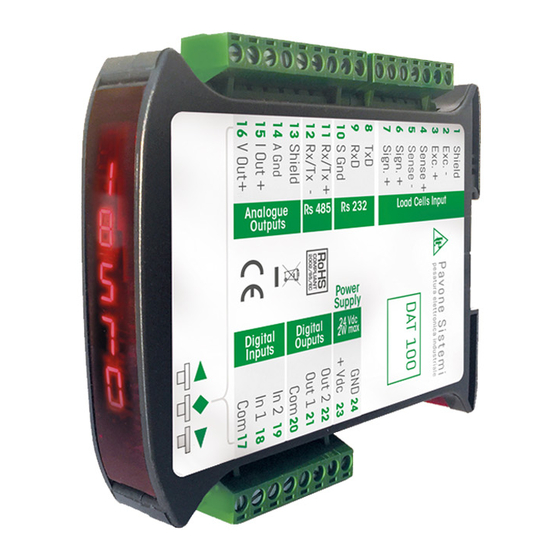
INTRODUCTION The DAT 100 is a weight transmitter to be matched to the load cells to detect the weight in every situation. The module is easy to install and can be mounted on 35 mm DIN rail. The display allows easy reading of the weight, the configuration parameters and errors. -
Page 6: Technical Features
Relay load Max. 1A, 24 Vdc/Vca Logic Inputs (DAT 100/A) No. 2 opto-isolated Serial ports RS232 half duplex RS485 half duplex (DAT 100/RS485) Baud rate 2400 ÷ 115200 baud Maximum cable length 15m (RS232) and 1000m (RS485) Analog output (DAT 100/A) Voltage: ±... -
Page 7: Installation
The DAT 100 consists of a motherboard, to which are added the options available, accommodated in a plastic enclosure for DIN rail 35mm. The DAT 100 should not be immersed in water, subjected to jets of water and cleaned or washed with solvents. - Page 8 2 with 5 and 3 with 4 . Connect the cell cable shield to the terminal 1. In the case of the usage of two or more load cells, use special jun- ction boxes (CEM4/C or CSG4/C). J-BOX CGS4/C DAT 100 +EXC +EXC -SGN SIGN-...
- Page 9 LOGIC INPUTs The two logic inputs are opto-isolated. The connection cable should not be channeled with power cables . The function of the two inputs is as follows: INPUT 1* TARE/ZERO INPUT 2 PRINT The activation of the two functions is accomplished by bringing the external 24 VDC power supply to the corresponding terminals as shown in the figure here beside.
- Page 10 DAT 100/A TRANSMITTER ANALOG OUTPUT The instrument provides an analog output in current and voltage. Analog voltage output: range from -10 to +10 V or -5 to +5 volts, 10K ohm minimum load. Analog current output: range from 0 to 20 mA or 4 to 20 mA. The maximum load is 300Ω.
-
Page 11: Front Panel
FRONT PANEL The DAT 100 transmitter has a front door that protects the 5 digits display, the 2 status LEDs and the three front keys. In operating mode the display shows the weight and the LEDs indicate the status of weight (net-gross). - Page 12 hardware DAT 100/RS485 module rS485 hardware DAT 100/A module ANALG It’s important to communicate these data in the event of a request for assistance. ERRORS NOTIFICATION In the operating mode, the display can report the following error codes.
-
Page 13: Viewing, Zeroing The Weight And Autotare
VIEWING, ZEROING THE WEIGHT AND AUTO TARE When the instrument is switched ON, the display shows the current net weight. VIEWING THE NET WEIGHT/GROSS WEIGHT Press the key to toggle between the net weight to gross weight and vice versa. The value displayed is reported by the LED 1 (lit: net weight). - Page 14 The calculated peak is not retained at power off. ▼ ▼ WEIGHT SETPOINT SET UP (ONLY DAT 100/A) The set point values are compared to the weight to drive its logic output. The comparison criteria is established in the set up procedure of the logic I / O (see relevant paragraph).
-
Page 15: Set-Up
SET UP GENERAL INFO All functions of the DAT 100 can be and amended through a simple setup menu, shown on the next page. All the settings activated or selected are stored even after switching off the transmitter. The DAT 100 is factory set. See the “default” parameters on the following pages. -
Page 16: Flow Chart Menu
FLOW CHART MENU Normal View ▲ ▲ ▲ ▲ ▲ ▲ 3 sec. ◆ ☞ ▼ ▼ ▼ ▼ ▼ ▼ ▼ ◆ ◆ ◆ ◆ ◆ ◆ ▲ ▼ ◆ ▲ ▼ ▲ ▼ ▲ ▼ ▲ ▼ ▲ ▼... - Page 17 CONFIGURATION PARAMETERS Through the setting of the parameters listed below, the DAT 100 Full Scale datasheet calibration is performed. You must complete these steps with the zero calibration described on the next page. The procedure ensures, in the absence of mechanical problems, a good accuracy of the system (maximum error <1% FS).
- Page 18 CALIB - CALIBRATION The calibration method below, is used to correct or reduce the linearity error of the weighing system. The calibration should be performed with the use of sample weight or pre-weighed product on a sample weighing system. Before proceeding with the calibration of the full scale, always perform the zero calibration. During the calibration phase, the display shows the weight intermittently with the inscription CAL.
-
Page 19: Analog Output Menu
PARAM - WEIGHING PARAMETERS The parameters in this menu allow to adjust the timing of the acquisition and updating of the display and the manual or automatic zeroing that the transmitter performs. f1Lt WEIGHT FILTER This parameter adjusts the refresh speed of the display and the ▲... - Page 20 ▼ ▲ Otrac TRACKING THE ZERO ◆ Enter Value ◆ This function allows a momentary zero calibration compensating the eventual temperature drift of the weight. ▼ ▲ At power off it automatically returns to the previous calibration. The maximum weight resettable by this parameter is 2% of the range of the system.
- Page 21 SER - SETTING THE SERIAL COMMUNICATION PORTS CON1 COM1: It defines the use of the COM1 serial port. ▲ ▲ ▲ None: Serial communication OFF Contn: Continuous transmission of the weight string. It can be used, for example, to drive a remote display. See details in the relevant ▼...
- Page 22 ▲ ▼ frN-1 COM1 DATA FORMAT Select Value ◆ ◆ It defines the data format of the RS232 serial port. The value must be set to the same value of the PC / PLC or remote ▲ ▼ display. In the case of MODBUS or SLAVE protocol, selections of the 7-bit data formats (E-7-1 and O-7-1) are not accepted (error message Select Value ◆...
- Page 23 ▲ ▼ Parameters only for dat 100/rs485 Select Value ◆ ◆ CON2 COM2: It defines the use the COM2 serial port. None: Serial communication OFF ▲ ▼ Contn: Continuous transmission of the weight string. It can be used, for example, to drive a remote display. See details in the relevant paragraph.
- Page 24 ▲ ▼ frN-2 COM2 DATA FORMAT Select Value ◆ ◆ It defines the COM2 serial port data format. The value must be set to the same value of the PC / PLC or remote ▲ ▼ display. In the case of MODBUS or SLAVE protocol, selections of the 7-bit data formats (E-7-1 and O-7-1) are not accepted (error message Select Value ◆...
- Page 25 INOUT - LOGIC INPUTS AND OUTPUT (DAT 100/A ONLY) NodE1 SETPOIN 1 OPERATION MODE ▲ ▲ ▲ Select 4 operation criterias of the SET POINT 1 in sequence: The relay output is active in Net Weight mode ...
- Page 26 hyst2 HYSTERESIS OF THE SET POINT 2 Hysteresis value compared to the SET POINT value Values: from 000 to 999 Default: 2 tst1n LOGIC INPUTS TEST PROCEDURE The display shows the Inputs status. 0 = input disabled 1= input activated. The Input 1 corresponds to the 1 st value on the bottom.
- Page 27 ANALG - ANALOG OUTPUT PARAMETERS (DAT 100/A ONLY) fsCal FULL SCALE ▲ ▲ ▲ It’s the weight corresponding to the full scale of the analog Output that can be different from the capacity of the weighing system. Values from 000 to 99999.
-
Page 28: Serial Communication Protocols
The COM1 RS232 serial port is always available, while the COM2 RS485 serial port is only available in the instrument: DAT 100 /RS485. On the COM2 RS485 the serial transmission protocols and the MODBUS RTU protocol are handled. CONTINUOUS, AUTOMATIC AND MANUAL TRANSMISSION PROTOCOL These protocols have been programmed into their programming menu. - Page 29 REQUEST OF THE CURRENT GROSS WEIGHT Master: <Addr> “L” EOT DAT 100: <Addr> “L” <status> <gross> ETX <chksum> EOT REQUEST OF THE CURRENT NET WEIGHT Master: <Addr> “N” EOT DAT 100: <Addr> “N” <status> <net> ETX <chksum> EOT REQUEST OF THE CURRENT PEAK VALUE Master: <Addr>...
- Page 30 CONTROL OF THE SET POINTS STORAGE IN PERMANENT MEMORY Master: <Addr> “E” EOT DAT 100: <Addr> “E” ACK EOT In the case of communication error or otherwise unrecognized command from DAT 100, it will respond with the following string: DAT 100: <Addr> NAK EOT FIELDS DESCRIPTION The double quotes enclose constant characters (observe upper and lower case);...
- Page 31 <Outputs>, <Inputs> = field consisting of only 1 ASCII character coed as per the table below (bit = 1 if Output/Input ON) Bit 7 Bit 6 Bit 5 Bit 4 Bit 3 Bit 2 Bit 1 Bit 0 Input 2 / Input 1 / Output 2 Output 1...
- Page 32 MODBUS RTU PROTOCOL For any hardware configuration of the instrument (RS485 or Ana), the MODBUS RTU protocol is always available on COM1 RS232; in the event of hardware DAT 100 / RS485, the MODBUS RTU protocol is also available on COM2 RS485.
- Page 33 41105 Zero tracking factor 41106 Zero band 41107 Weight Delta 41201 Operation mode of the thersold 1 R/W See relevant table. Used only for DAT 100 ANA. 41202 Hysteresis of the SET POINT 1 R/W FLOAT value. Used only for DAT 100 ANA.
- Page 34 WARNING: bits 13, 12, 11 and 10 are managed only in the event of hardware version DAT 100/A, in the other hardware versions these bits are always 0. COMMAND REGISTER CODING TABLE FOR MODBUS PROTOCOL Register value...
- Page 35 NOTES ON THE OPERATION OF THE ANALOG OUTPUT LIMITS When the weight exceeds the analog full-scale, the output takes a positive saturation value of about 10.7 V for the voltage output and 21.2 mA for current output. When the weight is negative or in an error condition, the output takes a negative saturation value of about -10.5 V for the voltage output and -0.2 mA for current output.
-
Page 36: Troubleshooting
TROUBLESHOOTING PROBLEM POSSIBLE CAUSE SOLUTION The weight gained is not detectable The display shows the because the cell is absent or Check the connections of the cells. O-L message. incorrectly connected The weight gained cannot be shown The display shows the because it exceeds the available five upper hyphen on the digits or is greater than the capacity... - Page 37 20863 Concorezzo, MB declare that the DoC issued under our sole responsibility and belongs to the following product: Apparatus model/Product: DAT 100 Type: Weighing instrument The object of the declaration described above used as indicated in the installation manual and use, is...
- Page 38 PAVONE SISTEMI S.R.L. Via Tiberio Bianchi, 11/13/15, 20863 Concorezzo (MB) T 039 9162656 F 039 9162675 W en.pavonesistemi.it Industrial Electronic Weighing Systems since 1963...
Need help?
Do you have a question about the DAT 100 and is the answer not in the manual?
Questions and answers