Table of Contents
Advertisement
SAM E54
SAME54 Curiosity Ultra Users Guide DM320210
Introduction
The SAM E54 Curiosity Ultra Development Board (DM320210) includes an integrated programmer and debugger,
hence additional hardware is not required to get started. Users can add functionality through MikroElectronika
™
™
™
mikroBUS
Click
adapter boards, add Ethernet connectivity with the Microchip PHY Daughter Board, add Wi-Fi
connectivity capability using the Microchip expansions boards, and add audio input and output capability with
Microchip audio daughter boards.
With or without expansion boards, the SAM E54 Curiosity Ultra Development Board provides the freedom to develop
®
for a variety of applications, including Bluetooth
Audio, CAN, Graphics User Interface (GUI), Internet of Things (IoT),
robotics development, and proof-of-concept (PoC) designs.
DS70005405A-page 1
©
2019 Microchip Technology Inc.
Advertisement
Table of Contents

Related Manuals for Microchip Technology SAM E54


Summary of Contents for Microchip Technology SAM E54
-
Page 1: Introduction
Microchip expansions boards, and add audio input and output capability with Microchip audio daughter boards. With or without expansion boards, the SAM E54 Curiosity Ultra Development Board provides the freedom to develop ® for a variety of applications, including Bluetooth Audio, CAN, Graphics User Interface (GUI), Internet of Things (IoT), robotics development, and proof-of-concept (PoC) designs. - Page 2 Arduino Uno R3 compatible interface Kit Contents The development board kit contains one SAM E54 Curiosity Ultra development board (DM320210). Note: If you are missing any part of the kit, contact a Microchip sales office for assistance. A list of Microchip offices for sales and service is provided on the last page of this document.
-
Page 3: Table Of Contents
SAM E54 Table of Contents Introduction..............................1 SAM E54 Curiosity Ultra Development Board Functionality and Features..........4 Hardware...............................19 The Microchip Website..........................32 Product Change Notification Service......................32 Customer Support............................32 Product Identification System........................33 Microchip Devices Code Protection Feature....................33 Legal Notice..............................33 Trademarks..............................34 Quality Management System........................ -
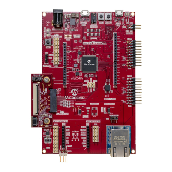
Page 4: Sam E54 Curiosity Ultra Development Board Functionality And Features
SAM E54 Curiosity Ultra Development Board Functionality and Features The SAM E54 Curiosity Ultra development board features and functionalists are given in the following sections. SAM E54 Curiosity Ultra Development Board Features Figure 1-1. SAM E54 Curiosity Ultra Development Board Layout (Top View) Table 1-1. SAM E54 Curiosity Ultra Development Board Feature Descriptions... - Page 5 SAM E54 SAM E54 Curiosity Ultra Development Board ....continued Number Description of item Ethernet interface (RMII, SPI, GPIO). X32 audio interface. 2 per board. Bluetooth & audio codecs sold separately CAN interface Graphics interface DAC output Audio reference clock select...
- Page 6 SAM E54 SAM E54 Curiosity Ultra Development Board ... System Block Diagram The following figure illustrates the system block diagram, which indicates the data bus routing. Figure 1-2. System Block Diagram EDBG/ SPI0 (SCK, SDI, SDO) EXT1 PKoB SPI0_SS_GPIO1 UART2_2w (ADC,GPIO,PWM, I2C6 IRQ,UART_2w) SPI0_SS_GPIO3...
- Page 7 Power Block Diagram The following diagram shows the power system on the SAM E54 Curiosity Ultra development board. The development board has many power sub systems that allow it to accept up to 16V. The barrel jack is a 2.1 mm center positive connector.
- Page 8 SAM E54 Curiosity Ultra Development Board ... EDBG The SAM E54 Curiosity Ultra development board implements several Curiosity Pro standards, such as extension headers and connectors. Curiosity Pro is an evaluation platform that provides a full Microchip microcontroller experience. The platform consists of a series of Microcontroller (MCU) boards and extension boards that are ®...
- Page 9 SAM E54 SAM E54 Curiosity Ultra Development Board ... Table 1-3. Xplained Pro ID Chip Content Example Data Field Data Type Example Manufacture ASCII string Microchip’\0’ Product Name ASCII string Product Revision ASCII string 04’\0’ Product Serial number ASCII string 1774020200000010’\0’...
- Page 10 SAM E54 SAM E54 Curiosity Ultra Development Board ... Audio Clock Selection The SAM E54 has two ways of supporting I S audio applications: Host mode and Slave mode. This refers to which mode generates the I S Master clock, and it also known as a reference clock. The following figure shows the relationship between the devices.
- Page 11 SAM E54 SAM E54 Curiosity Ultra Development Board ....continued Pin Number Name Description Interface C SDA Data line for I C interface. Audio WS/LRCLK Audio Word Select/Left Right Clock Audio In Audio into MCU, out from codac Audio CLK...
- Page 12 SAM E54 SAM E54 Curiosity Ultra Development Board ....continued Interface Reset PC18 REFCLK PA08/PA17 (refer to Figure 1-4 Audio Clock Selection) S Clock PA10 S Audio Out (MOSI) PA11 S Audio In (MISO) PB10 S LRCLK PA09 mikroBUS The mikroBUS interface enables using additional click boards. For more information, and to see the boards that can be used with this development board follow the link: https://www.mikroe.com/.
- Page 13 SAM E54 SAM E54 Curiosity Ultra Development Board ... Xplained Pro Standard Extension Header All Xplained Ultra and Curiosity Ultra Kits have many dual-row, 20-pin, and 100 mil extension headers. Xplained Ultra and Curiosity Ultra MCU boards have male headers, while Xplained Ultra extensions have their female counterparts as shown in the following figure.
- Page 14 Graphics Connectors or GFX Card Interface The SAM E54 Curiosity Ultra development kit is designed to have a modular graphics interface. This interface enables the use of several different graphics cards, which allows for expandability and different use cases. A 24-bit pass though card is included with the kit, this board passes parallel data through, and can be configured to an 8-bit 8080 MCU mode.
- Page 15 SAM E54 SAM E54 Curiosity Ultra Development Board ....continued Pin Number Name Description SPI SS SPI Slave Select LCD D5 LCD Data bit 5 UART RX Receiver line of target device UART LCD D6 LCD Data bit 6 UART TX Transmitter line of target device UART.
- Page 16 Mounting Tab Ethernet The SAM E54 Curiosity Ultra development kit has a modular Ethernet PHY system that enables different PHYs to be plugged into the board. This interface is setup to use a Reduced Media-Independent Interface (RMII) and a SPI bus interface with GPIO.
- Page 17 SAM E54 SAM E54 Curiosity Ultra Development Board ... Figure 1-6. Ethernet PHY Header Configuration The following table provides the Ethernet PHY interface pinout descriptions. Table 1-8. Ethernet Interface Pinout Description Pin Number Name Description GPIO General purpose I/O GPIO General purpose I/O...
- Page 18 SAM E54 SAM E54 Curiosity Ultra Development Board ....continued Pin Number Name Description 15 (3) TDX1 Transmit Data 16 (4) MOSI Master Out Slave In line of serial peripheral interface 17 (5) MISO Master In Slave Out line of serial peripheral interface...
-
Page 19: Hardware
SAM E54 Hardware Hardware Schematics SAM E54 Curiosity Ultra U_SHT_4_Target_MCU_R2 U_SHT_5_Shield Headers_R2 SHT_4_Target_MCU_R2.SchDoc SHT_5_Shield Headers_R2.SchDoc TARGET_RESETN SHIELD_ANA SHIELD_ANA U_SHT_2_Power_R2 SHIELD_DIG SHIELD_DIG SHT_2_Power_R2.SchDoc TARGET_RESETN TARGET_USB_P TARGET_USB_P AREF AREF TARGET_USB_N TARGET_USB_N U_SHT_9_MikroBUS and X32 Audio_R2 OTG_SW OTG_SW SHT_9_MikroBUS and X32 Audio_R2.SchDoc USB_ID_DET... - Page 20 SAM E54 Hardware R220 4.7R R205 R206 R204 2.2R R203 R221 2.2R DS70005405A-page 20 © 2019 Microchip Technology Inc.
- Page 21 SAM E54 Hardware R326 R316 6.81k DS70005405A-page 21 © 2019 Microchip Technology Inc.
- Page 22 SAM E54 Hardware USER_BUTTON2 R473 2.2k 330R R470 R469 USER_BUTTON1 ETHERNET MikroBUS SD_CARD AUDIO DAC_OUT EXT1 R421 R420 R419 R418 DGI_SPI QSPI DS70005405A-page 22 © 2019 Microchip Technology Inc.
- Page 23 SAM E54 Hardware DIGITAL (~PWM) POWER ANALOG IN DS70005405A-page 23 © 2019 Microchip Technology Inc.
- Page 24 SAM E54 Hardware TRACE DAC_OUT DS70005405A-page 24 © 2019 Microchip Technology Inc.
- Page 25 SAM E54 Hardware QSPI SD_CARD DS70005405A-page 25 © 2019 Microchip Technology Inc.
- Page 26 SAM E54 Hardware SLM-112-01-L-S SLM-103-01-L-S SLM-112-01-L-S SLM-103-01-L-S DS70005405A-page 26 © 2019 Microchip Technology Inc.
- Page 27 SAM E54 Hardware R903 DS70005405A-page 27 © 2019 Microchip Technology Inc.
- Page 28 SAM E54 Hardware DS70005405A-page 28 © 2019 Microchip Technology Inc.
- Page 29 J503 SSQ-110-21-F-S 1x10 receptacle pin header, low insertion force, 2.54mm pitch THM, Pin in Paste J600 1125-1103S0S113R1 1x3 pin Header, 2.54mm pitch, TH J601, J902 HMTSW-110-23-F-D-237 2x10 pin header, 2.54mm pitch, Pin-in-Paste THM DS70005405A-page 29 © 2019 Microchip Technology Inc.
- Page 30 RES 2.49K OHM 1% 1/16W 0402 RES 2.49K OHM 1% 1/16W 0402 R211 RES SMD 475 OHM 1% 1/16W 0402 RES SMD 475 OHM 1% 1/16W 0402 R215, R216 Thick film resistor, SMD 0402, 1/16W, 1% DS70005405A-page 30 © 2019 Microchip Technology Inc.
- Page 31 XC300 12.00MHz Fox FQ5032B 12.0000MHz 20pF SMD crystal 738B-12 Y400 OSCILLATOR 32.768KHz OSCILLATOR 32.768KHz 1.71-3.3V DSC60xxL3.2xW2.5H0.9 DSC60xxL3.2xW2.5H0.90 Y401 OSCILLATOR 12.000MHz OSCILLATOR 12.000MHz 1.71-3.3V DSC60xxL3.2xW2.5H0.9 DSC60xxL3.2xW2.5H0.90 Y800 OSCILLATOR 50MHz OSCILLATOR 50MHz 1.71-3.3V DSC60xxL3.2xW2.5H0.9 DSC61xxL3.2xW2.5H0.90 DS70005405A-page 31 © 2019 Microchip Technology Inc.
-
Page 32: The Microchip Website
Customers should contact their distributor, representative or ESE for support. Local sales offices are also available to help customers. A listing of sales offices and locations is included in this document. Technical support is available through the web site at: http://www.microchip.com/support DS70005405A-page 32 © 2019 Microchip Technology Inc. -
Page 33: Product Identification System
Information contained in this publication regarding device applications and the like is provided only for your convenience and may be superseded by updates. It is your responsibility to ensure that your application meets with your specifications. MICROCHIP MAKES NO REPRESENTATIONS OR WARRANTIES OF ANY KIND WHETHER DS70005405A-page 33 © 2019 Microchip Technology Inc. -
Page 34: Trademarks
The Adaptec logo, Frequency on Demand, Silicon Storage Technology, and Symmcom are registered trademarks of Microchip Technology Inc. in other countries. GestIC is a registered trademark of Microchip Technology Germany II GmbH & Co. KG, a subsidiary of Microchip Technology Inc., in other countries. -
Page 35: Worldwide Sales And Service
New York, NY Tel: 46-31-704-60-40 Tel: 631-435-6000 Sweden - Stockholm San Jose, CA Tel: 46-8-5090-4654 Tel: 408-735-9110 UK - Wokingham Tel: 408-436-4270 Tel: 44-118-921-5800 Canada - Toronto Fax: 44-118-921-5820 Tel: 905-695-1980 Fax: 905-695-2078 DS70005405A-page 35 © 2019 Microchip Technology Inc.
Need help?
Do you have a question about the SAM E54 and is the answer not in the manual?
Questions and answers