Table of Contents
Advertisement
Quick Links
SAM E70 Xplained Ultra User's Guide
Introduction
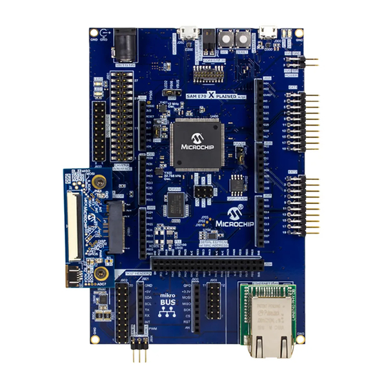
This user's guide provides detailed information about the SAM E70 Xplained Ultra Evaluation kit and its
various features. Figure below illustrates the SAM E70 Xplained Ultra Evaluation kit.
Figure 1. SAM E70 Xplained Ultra Evaluation Kit with PHY Daughter Board
Features
• ATSAME70Q21 Microcontroller
• One Mechanical Reset Button
• One Mechanical User Push Button
• Two User LEDs
• 12.0 MHz Oscillator (DSC6003)
• 32.768 kHz Oscillator (DSC6083)
• 2-MB SDRAM
• 4-MB QSPI Flash (SST26VF032BA)
©
2019 Microchip Technology Inc.
DS70005389A-page 1
Advertisement
Table of Contents

Related Manuals for Microchip Technology SAM E70 Xplained Ultra


Summary of Contents for Microchip Technology SAM E70 Xplained Ultra
-
Page 1: Introduction
SAM E70 Xplained Ultra User's Guide Introduction This user’s guide provides detailed information about the SAM E70 Xplained Ultra Evaluation kit and its various features. Figure below illustrates the SAM E70 Xplained Ultra Evaluation kit. Figure 1. SAM E70 Xplained Ultra Evaluation Kit with PHY Daughter Board Features •... - Page 2 For a free Microchip demonstration code and additional information, visit the MPLAB Harmony page at: http://www.microchip.com/MPLABHarmony. The Atmel SAM E70 Xplained Ultra Dvelopment Kit is a hardware platform to evaluate the Microchip ATSAME70Q21. The kit offers a set of features that enables the ATSAME70Q21 users to start with the SAM E70 peripherals and understand how to integrate the device in their design.
- Page 3 Figure 2. SAM E70 Xplained Ultra Evaluation Kit DS70005389A-page 3 © 2019 Microchip Technology Inc.
- Page 4 The table below provides the SAM E70 Xplained Ultra Evaluation kit feature descriptions. Table 1. SAM E70 Xplained Ultra Evaluation Kit Feature and Location Number Description CAN interface X32 Daughter Board interface Mikro interface Ethernet PHY interface Ethernet Clock enable/disable jumper...
-
Page 5: Table Of Contents
5.12. Switches............................. 24 5.13. AT24MAC402 Serial EEPROM....................25 5.14. Power Sources........................... 26 6. Hardware......................... 28 6.1. SAM E70 Xplained Ultra Development Board Schematics............28 6.2. Bill of Materials........................... 50 The Microchip Web Site....................55 Customer Change Notification Service................55 Customer Support......................55 Microchip Devices Code Protection Feature.............. -
Page 6: Getting Started
™ Install MPLAB Harmony 3 When Microchip SAM E70 Xplained Ultra is connected to the computer for the first time, the operating ® system will install a driver software. The driver file supports both 32-bit and 64-bit versions of Microsoft ®... - Page 7 Getting Started – Package containing schematics, BOM, assembly drawings, 3D plots, layer plots, and so on. • Hardware Users Guide – PDF version of this user guide. DS70005389A-page 7 © 2019 Microchip Technology Inc.
-
Page 8: Xplained Ultra
Xplained Ultra Xplained Ultra The SAM E70 Xplained Ultra implements several Xplained Pro standards like extension headers and connectors. Xplained Pro is an evaluation platform that provides a full Microchip microcontroller experience. The platform consists of a series of Microcontroller (MCU) boards and extension boards that are integrated with the Microchip MPLAB IDE that supports data streaming. -
Page 9: Embedded Debugger
The Data Visualizer is used to send and receive data through DGI. The EDBG controls two LEDs on SAM E70 Xplained Ultra: a power LED and a status LED. The following table describes how the LEDs are controlled in different operation modes. - Page 10 Manufacture ASCII string Microchip’\0’ Product Name ASCII string Product Revision ASCII string 04’\0’ Product Serial number ASCII string 1774020200000010’\0’ Minimum Voltage (mV) uint16_t 3000 Maximum Voltage (mV) uint16_t 3600 Maximum Current (mA) uint16_t DS70005389A-page 10 © 2019 Microchip Technology Inc.
-
Page 11: System Level Block Diagram
System Level Block Diagram System Level Block Diagram The following figure illustrates the high-level signal block diagram of the SAM E70 Xplained Ultra Development Kit. Figure 4-1. Signal Level Block Diagram Wire buses that are tied together are connected together. In this system the SPI bus data and clock are shared across several interfaces. -
Page 12: Hardware Features
SPI SS B/GPIO SPI Slave Select or general purpose I/O C SDA Data line for I C interface. Always implemented, bus type C SCL Clock line for I C interface. Always implemented, bus type UART RX Receiver line of target device UART DS70005389A-page 12 © 2019 Microchip Technology Inc. -
Page 13: Graphics Connectors Or Gfx Card Interface
Power for extension boards (3.3V) Graphics Connectors or GFX Card Interface The SAM E70 Xplained Ultra Development Kit is designed to have a modular graphics interface. This interface enables using several graphics cards, which allow for expandability and different use cases. A 565 adapter card is included in the kit, which takes 16-bit parallel LCD data and converts it to 24-bit data. - Page 14 LCD Data bit 11 GPIO1 General purpose I/O LCD D12 LCD Data bit 12 GPIO2 General purpose I/O LCD D13 LCD Data bit 13 GPIO3 General purpose I/O LCD D14 LCD Data bit 14 DS70005389A-page 14 © 2019 Microchip Technology Inc.
- Page 15 LCD D23 LCD Data bit 23 ADC6 Analog-to-Digital Converter to MCU 3.3V V +3.3V V ADC7 Analog-to-Digital Converter to MCU Ground 3.3V V +3.3V V Ground GND TAB Mounting Tab GND TAB Mounting Tab DS70005389A-page 15 © 2019 Microchip Technology Inc.
-
Page 16: Sdram And Lcd Connections
EBI tracks on the PCB using series resistors. The EBI tracks are routed as 50Ω on SAM E70 Xplained Ultra. The clock and address lines are only driven by the ATSAME70Q21B, while the data lines are driven by the ATSAME70Q21B and the on-board SDRAM. - Page 17 LCD connector. • All designs must be simulated using an IBIS file for the ATSAMV71Q21B and the target peripherals to check whether the signals are within the limits of the devices. DS70005389A-page 17 © 2019 Microchip Technology Inc.
-
Page 18: Camera Connector
Image Sensor Data Bit 6 ISI D7 Image Sensor Data Bit 7 ISI D8 Image Sensor Data Bit 8 ISI D9 Image Sensor Data Bit 9 ISI D10 Image Sensor Data Bit 10 DS70005389A-page 18 © 2019 Microchip Technology Inc. -
Page 19: Usb Connectivity
SAM E70 The SAM E70 Xplained Ultra has a Micro-USB connector to use with the SAM E70 USB module labeled as TARGET USB on the kit. In USB Host mode, the VBUS voltage is provided by the kit, and must be enabled by setting the VBUS Host Enable pin to low. -
Page 20: Chip Erase Header
SSC and the I S. Addition to this other control lines and data interfaces are available. Figure 5-4. SSC/I S Block Diagram Table 5-7. X32 Audio Interface Pin Description Pin Number Name Description Interface Ground Power DS70005389A-page 20 © 2019 Microchip Technology Inc. - Page 21 Audio into MCU, out from CODEC 26 (6) 27 (7) Audio OUT Audio out of MCU, in to CODEC/DAC 28 (8) 29 (9) REFCLK2/MCK2 Reference clock #2 REFCLK 30 (10) 31 (11) Ground DS70005389A-page 21 © 2019 Microchip Technology Inc.
-
Page 22: Mikrobus ™ Header
Xplained Ultra has two MCAN modules that perform communications according to ISO11898-1 (Robert Bosch GmbH CAN specification 2.0 part A and B). Bosch CAN FD specification V1.0. MCAN1 is connected to an on-board ATA6561 CAN physical-layer transceiver. These connections are described in the following table. DS70005389A-page 22 © 2019 Microchip Technology Inc. -
Page 23: Ethernet
5.10 Ethernet The SAM E70 Xplained Ultra kit has a modular Ethernet PHY system that allows for different PHYs to be plugged into the board. This interface is set up to use a Reduced Media-Independent Interface (RMII), as well as a SPI bus interface with GPIO. -
Page 24: Debug Usb Connectivity
This enables the user to investigate the software debounce techniques. When Idle, the switches are pulled high (+3.3V,) and when pressed, they are grounded. DS70005389A-page 24 © 2019 Microchip Technology Inc. -
Page 25: At24Mac402 Serial Eeprom
Microchip MPLAB Xplained window or Atmel Studio Xplained window after the kit has been plugged into the PC. Figure 5-6. SAM E70 Xplained Ultra Window Note: The above figure provides an example of the Xplained window with the MAC48 address. -
Page 26: Power Sources
• Using the 2 x 2 x 0.1 header, located on the side of the board, which has a 3.3v and 5.0v capable inputs. The SAM E70 Xplained Ultra kit can be powered by several power sources as described in the following table. - Page 27 Hardware Features Table 5-11. Power Sources for SAM E70 Xplained Ultra Connector Power Input Voltage Requirements Current Requirements Marking External Power 5V ±2% (±100 mV) for USB Recommended minimum current is host operation. 4.3V to 5.5V if 1A to be able to provide enough...
-
Page 28: Hardware
Hardware Hardware SAM E70 Xplained Ultra Development Board Schematics DS70005389A-page 28 © 2019 Microchip Technology Inc. - Page 29 Hardware DS70005389A-page 29 © 2019 Microchip Technology Inc.
- Page 30 Hardware DS70005389A-page 30 © 2019 Microchip Technology Inc.
- Page 31 Hardware DS70005389A-page 31 © 2019 Microchip Technology Inc.
- Page 32 Hardware DS70005389A-page 32 © 2019 Microchip Technology Inc.
- Page 33 Hardware DS70005389A-page 33 © 2019 Microchip Technology Inc.
- Page 34 Hardware DS70005389A-page 34 © 2019 Microchip Technology Inc.
- Page 35 Hardware DS70005389A-page 35 © 2019 Microchip Technology Inc.
- Page 36 Hardware DS70005389A-page 36 © 2019 Microchip Technology Inc.
- Page 37 D19_LCD PC31 ADC2 AFE1 AD06 PIN54_D20 D20_LCD PC13 ADC3 AFE1 AD1 PIN56_D21 D21_LCD ADC4 PIN58_D22 D22_LCD ADC5 PIN60_D23 D23_LCD ADC6 PIN62_D24 ADC7 VCC_P3V3 PIN64_D25 100k R1001 VCC_P3V3 PIC32 GFX CONNECTOR W_MOUNTING LOC ID3/ID4 DS70005389A-page 37 © 2019 Microchip Technology Inc.
- Page 38 Hardware DS70005389A-page 38 © 2019 Microchip Technology Inc.
- Page 39 Hardware DS70005389A-page 39 © 2019 Microchip Technology Inc.
- Page 40 Hardware DS70005389A-page 40 © 2019 Microchip Technology Inc.
- Page 41 Hardware DS70005389A-page 41 © 2019 Microchip Technology Inc.
- Page 42 Hardware DS70005389A-page 42 © 2019 Microchip Technology Inc.
- Page 43 Hardware DS70005389A-page 43 © 2019 Microchip Technology Inc.
- Page 44 Hardware DS70005389A-page 44 © 2019 Microchip Technology Inc.
- Page 45 Hardware DS70005389A-page 45 © 2019 Microchip Technology Inc.
- Page 46 Hardware DS70005389A-page 46 © 2019 Microchip Technology Inc.
- Page 47 Hardware DS70005389A-page 47 © 2019 Microchip Technology Inc.
- Page 48 Hardware DS70005389A-page 48 © 2019 Microchip Technology Inc.
- Page 49 Hardware DS70005389A-page 49 © 2019 Microchip Technology Inc.
-
Page 50: Bill Of Materials
D201, D202, D203, D204 2A, 30V,Vf = 0.43V, Schottky diode, SOD-123 FL D205, D301 LED, Green, Wave length = 575nm, SMD 0805, ±70° D302, D400 LED, Yellow, Wave length = 5 91nm, SMD 0805, ±70° DS70005389A-page 50 © 2019 Microchip Technology Inc. - Page 51 2.2 µH Shielded Power Inductor, 4 x 4 x 2 mm, Isat = 5.6A , Irms © = 4 .0A , DCR = 35.2 mÎ MH1, MH2 Round Standoff Threaded M2.5 x 0.45 Steel 0.098 (H2.50 mm) DS70005389A-page 51 © 2019 Microchip Technology Inc.
- Page 52 Thick film resistor, 1M, SMD 0402, 1/16W, 1% R802 R206, R313, R314, R315, Thick film resistor, 1K, SMD 0402, 1/16W, 1% R411, R412 R209, R210, R215 Thick film resistor, 47K, SMD 0402, 1/16W, 1% DS70005389A-page 52 © 2019 Microchip Technology Inc.
- Page 53 16 Mbit SDRAM (512K Words x 16 Bits x 2 Banks), 143 MHz 3,3V U702 FLASH 32MBIT_8SOIC (W5.3 mm) SST26VF032BAT-104I/SM U800 High-speed CAN Transceiver with Standby mode CAN FD Ready XC300 Fox FQ5032B 12.0000 MHz 20pF SMD crystal 738B-12, Fox FQ5032B 12.0 MHz SMD crystal 738B-12 DS70005389A-page 53 © 2019 Microchip Technology Inc.
- Page 54 Oscillator 50 MHz 1.71-3.3V DSC60xxL3.2xW2.5H0.9 SW201, SW400 SWITCH, SMD, 260 gf, 6.4 mm X 6.2 mm E1, E2, E3, E4 2.8 mm adhesive feet, diam 8.0 mm S1, S2 M2.5 x 5 mm Pan Phillip Screw DS70005389A-page 54 © 2019 Microchip Technology Inc.
-
Page 55: The Microchip Web Site
Microchip’s Data Sheets. Most likely, the person doing so is engaged in theft of intellectual property. • Microchip is willing to work with the customer who is concerned about the integrity of their code. DS70005389A-page 55 © 2019 Microchip Technology Inc. -
Page 56: Legal Notice
SQTP is a service mark of Microchip Technology Incorporated in the U.S.A. Silicon Storage Technology is a registered trademark of Microchip Technology Inc. in other countries. GestIC is a registered trademark of Microchip Technology Germany II GmbH & Co. KG, a subsidiary of Microchip Technology Inc., in other countries. -
Page 57: Quality Management System Certified By Dnv
© 2019, Microchip Technology Incorporated, Printed in the U.S.A., All Rights Reserved. ISBN: 978-1-5224-4113-7 Quality Management System Certified by DNV ISO/TS 16949 Microchip received ISO/TS-16949:2009 certification for its worldwide headquarters, design and wafer fabrication facilities in Chandler and Tempe, Arizona; Gresham, Oregon and design centers in California ®... -
Page 58: Worldwide Sales And Service
Tel: 46-31-704-60-40 New York, NY Sweden - Stockholm Tel: 631-435-6000 Tel: 46-8-5090-4654 San Jose, CA UK - Wokingham Tel: 408-735-9110 Tel: 44-118-921-5800 Tel: 408-436-4270 Fax: 44-118-921-5820 Canada - Toronto Tel: 905-695-1980 Fax: 905-695-2078 DS70005389A-page 58 © 2019 Microchip Technology Inc.
Need help?
Do you have a question about the SAM E70 Xplained Ultra and is the answer not in the manual?
Questions and answers