
Subscribe to Our Youtube Channel
Related Manuals for Geokon 6150F


Summary of Contents for Geokon 6150F
- Page 1 Model 6150F MEMS Digital Addressable In-Place Inclinometer Instruction Manual ©2019, GEOKON. All rights reserved. Document Revision: Init | Release date: 8/6/19...
- Page 3 WARRANTY STATEMENT warrants its products to be free of defects in materials and workmanship, GEOKON under normal use and service for a period of 13 months from date of purchase. If the unit should malfunction, it must be returned to the factory for evaluation, freight prepaid.
-
Page 5: Table Of Contents
TABLE OF CONTENTS 1. INTRODUCTION ............................2. INSTALLATION .............................. 2.1 PRELIMINARY TESTS ........................2.2 ASSEMBLY ..............................2.2.1 SEGMENT ASSEMBLY ........................2.2.2 BOTTOM WHEEL ASSEMBLY ...................... 2.2.3 SENSOR ORIENTATION ........................2.2.4 SENSOR INSTALLATION ........................ 2.2.5 CONNECTING THE SUSPENSION BRACKET ................. 2.3 MODEL 8020-38 RS-485 TO TTL/USB CONVERTER .......... - Page 6 FIGURE 16: MALE WATERPROOF CONNECTOR ............7 FIGURE 17: FEMALE WATERPROOF CONNECTOR ............7 FIGURE 18: DEFLECTION INTERVALS ................11 FIGURE 19: SAMPLE MODEL 6150F CALIBRATION SHEET, SENSOR A ....16 FIGURE 20: SAMPLE MODEL 6150F CALIBRATION SHEET, SENSOR B ....17 FIGURE 21: ALLOWED DROPS GRAPHIC REPRESENTATION ........21...
- Page 7 TABLE 4: NON-VOLATILE MEMORY................. 9 TABLE 5: PREPROGRAMMED DEVICE INFORMATION ..........10 TABLE 6: MODEL 6150F INCLINOMETER SPECIFICATIONS........15 TABLE 7: MODEL 6150F INCLINOMETER PARTS LIST ..........15 TABLE 8: MODBUS COMMUNICATIONS PARAMETERS..........18 TABLE 9: ERROR CODES ....................18...
- Page 8 EQUATIONS EQUATION 1: CORRECTED INCLINATION ANGLE............11 EQUATION 2: CHANGE IN INCLINATION ...............11 EQUATION 3: LATERAL DISPLACEMENT................11 EQUATION 4: OFFSET CALCULATION................11 EQUATION 5: DEFLECTION CALCULATION..............12...
-
Page 9: Introduction
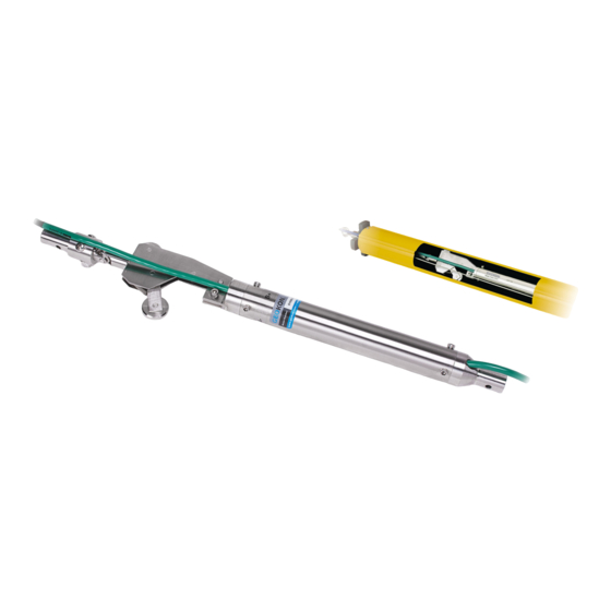
The entire string is normally supported from the top of the casing by a suspension bracket. FIGURE 1: Model 6150F Installed MODEL 6150F MEMS DIGITAL ADDRESSABLE IN-PLACE INCLINOMETER | INTRODUCTION | 1... -
Page 10: Installation
Once all sensors have been connected, plug the end terminator into the female connector at the bottom sensor. See the figure below. FIGURE 4: End Terminator Model 6150F-2 Connect the completed string to a readout or datalogger. Hold the first sensor in a vertical position and observe the reading. The tilt sensor must be held steady while taking the reading. -
Page 11: Assembly
2.2.2 BOTTOM WHEEL ASSEMBLY The bottom wheel assembly, Model 6300-5, has no universal joint, only a swivel. Attach this wheel assembly to the bottom segment using the provided hardware. MODEL 6150F MEMS DIGITAL ADDRESSABLE IN-PLACE INCLINOMETER | INSTALLATION | 3... -
Page 12: Sensor Orientation
A second MEMS device is included in the sensor and is attached with its positive direction 90° clockwise from the first device. This is the B+ direction of FIGURE 9: A & B Directions the sensor. 4 | INSTALLATION | GEOKON... -
Page 13: Sensor Installation
(sold separately), or use the connector tube provided. Eye Bolt Suspension Bracket Connector 150 mm Tube above ground level Below ground Casing FIGURE 11: Suspension via Cable FIGURE 12: Suspension via Tube MODEL 6150F MEMS DIGITAL ADDRESSABLE IN-PLACE INCLINOMETER | INSTALLATION | 5... -
Page 14: Model 8020-38 Rs-485 To Ttl/Usb Converter
■ If your datalogger has built-in RS-485 communications, connect the wiring using the diagram in Figure 15. FIGURE 14: Wiring of Datalogger without built-in RS-485 Conversion FIGURE 15: Wiring of Datalogger with built-in RS-485 Conversion 6 | INSTALLATION | GEOKON... -
Page 15: Six-Pin Waterproof Connector
FIGURE 16: Male Waterproof Connector FIGURE 17: Female Waterproof Connector Wire Color Function Power Black Ground White RS-485+ Data High Green RS-485- Data Low Bare Shield Drain TABLE 1: Six-Pin Wiring Chart MODEL 6150F MEMS DIGITAL ADDRESSABLE IN-PLACE INCLINOMETER | INSTALLATION | 7... -
Page 16: Modbus Rtu Protocol
MODBUS RTU PROTOCOL 3.1 INTRODUCTION TO MODBUS Model 6150F inclinometers use the industry standard Modbus Remote Terminal Unit (RTU) protocol to communicate with the chosen readout method. As the name suggests, Modbus was designed to work on what is known as a bus network, meaning that every device receives every message that passes across the network. -
Page 17: Table 2: Register Addresses And Formats
0x202 0x203 0x204 Sensor Type string 0x205 0x206 0x207 0x208 0x209 Serial Number uint32 0x20A 0x20B Software Version uint16 0x20C Hardware Version uint16 TABLE 4: Non-Volatile Memory MODEL 6150F MEMS DIGITAL ADDRESSABLE IN-PLACE INCLINOMETER | MODBUS RTU PROTOCOL | 9... -
Page 18: Table 5: Preprogrammed Device Information
Type Access 0x20D A Offset degrees float 0x20E 0x20F B Offset degrees float 0x210 0x213 A Gauge Factor degrees float 0x214 0x215 float B Gauge Factor degrees 0x216 TABLE 5: Preprogrammed Device Information 10 | MODBUS RTU PROTOCOL | GEOKON... -
Page 19: Data Reduction
DATA REDUCTION 4.1 INCLINATION CALCULATION The output of the Model 6150F inclinometer sensor is angle of inclination. The standard sensor has a full range of approximately ±15°. Each sensor is provided with a unique Gauge Factor (G) that is used to calculate θ... -
Page 20: Temperature Correction
12 | DATA REDUCTION | GEOKON... -
Page 21: Troubleshooting
□ Check all cable connections, terminals, and plugs. □ Water may have penetrated the interior of the tilt sensor. There is no remedial action. MODEL 6150F MEMS DIGITAL ADDRESSABLE IN-PLACE INCLINOMETER | TROUBLESHOOTING | 13... - Page 22 14 | TROUBLESHOOTING | GEOKON...
-
Page 23: Appendix A. Specifications
Bottom wheel assembly (one required per string) 6300-6E/M Rescue cable for in-place inclinometer, runs to bottom of assembly 6300-7 Tube Coupling 07-125SS-M Aircraft cable, 1/8" TABLE 7: Model 6150F Inclinometer Parts List MODEL 6150F MEMS DIGITAL ADDRESSABLE IN-PLACE INCLINOMETER | SPECIFICATIONS | 15... -
Page 24: Appendix B. Sample Calibration Sheets
APPENDIX B. SAMPLE CALIBRATION SHEETS FIGURE 19: Sample Model 6150F Calibration Sheet, Sensor A 16 | SAMPLE CALIBRATION SHEETS | GEOKON... -
Page 25: Figure 20: Sample Model 6150F Calibration Sheet, Sensor B
FIGURE 20: Sample Model 6150F Calibration Sheet, Sensor B MODEL 6150F MEMS DIGITAL ADDRESSABLE IN-PLACE INCLINOMETER | SAMPLE CALIBRATION SHEETS | 17... -
Page 26: Appendix C. Modbus Addressable System
Note: The sensor stores and transmits errors in binary code to compact the information. Though unlikely, two errors could occur in one measurement cycle. The resulting code will be the sum of the error numbers, e.g., error 4 plus error 8 appears as number 12. 18 | MODBUS ADDRESSABLE SYSTEM | GEOKON... -
Page 27: Appendix D. Crbasic Programming
APPENDIX D. CRBASIC PROGRAMMING D.1 SAMPLE CR1000 PROGRAM The following sample program reads one 6150F sensor string with three biaxial sensors. The string in this example communicates with the CR1000 through the control ports C1 and C2, which are setup as COM1. A RS-485 to TTL converter is required. - Page 28 'Use Modbus command to retrieve A Axis and B Axis Degree Readings ModbusMaster (ErrorCode,ComC1,115200,Count,3,A_Axis_Degrees(Count),&H101,1,1,10,0) ModbusMaster (ErrorCode,ComC1,115200,Count,3,B_Axis_Degrees(Count),&H103,1,1,10,0) 'Use Modbus command to retrieve Thermistor Celsius from string ModbusMaster (ErrorCode,ComC1,115200,Count,3,Celsius(Count),&H107,1,1,10,0) 'Delay before proceeding to next reading Delay (1,1,Sec) Next 'Call Table to store Data CallTable Test NextScan EndProg 20 | CRBASIC PROGRAMMING | GEOKON...
-
Page 29: Appendix E. Drops Versus Length
Note: The number of drops that can be supported on strings shorter than 200 meters must be handled on a case-by-case basis, and may require practical experimentation to obtain a reliable result. MODEL 6150F MEMS DIGITAL ADDRESSABLE IN-PLACE INCLINOMETER | DROPS VERSUS LENGTH | 21... - Page 32 GEOKON Phone: +1 (603) 448-1562 GEOKON 48 Spencer Street Email: info@geokon.com is an ISO 9001:2015 Lebanon, New Hampshire Website: www.geokon.com registered company 03766, USA...
Need help?
Do you have a question about the 6150F and is the answer not in the manual?
Questions and answers