Table of Contents
Advertisement
Quick Links
Instruction Manual
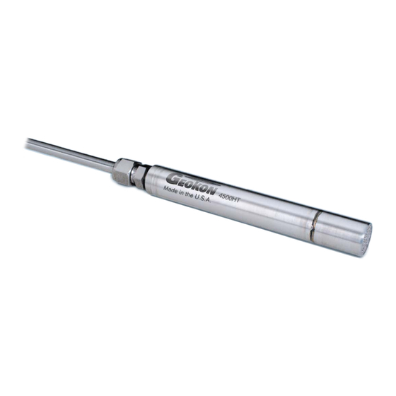
Model 4500HT
High Temperature
Vibrating Wire Piezometer
No part of this instruction manual may be reproduced, by any means, without the written consent of Geokon, Inc.
The information contained herein is believed to be accurate and reliable. However, Geokon, Inc. assumes no responsibility for
errors, omissions, or misinterpretation. The information herein is subject to change without notification.
Copyright © 2012-2018 by Geokon, Inc.
(Doc Rev C 06/28/18)
Advertisement
Table of Contents

Subscribe to Our Youtube Channel
Related Manuals for Geokon 4500HT


Summary of Contents for Geokon 4500HT
- Page 1 Vibrating Wire Piezometer No part of this instruction manual may be reproduced, by any means, without the written consent of Geokon, Inc. The information contained herein is believed to be accurate and reliable. However, Geokon, Inc. assumes no responsibility for errors, omissions, or misinterpretation.
- Page 3 Upon examination by Geokon, if the unit is found to be defective, it will be repaired or replaced at no charge. However, the WARRANTY is VOID if the unit shows evidence of having been tampered with...
-
Page 5: Table Of Contents
INERAL NSULATED ABLE A.3 T (TEC) ......................16 UBULAR NCAPSULATED ABLE APPENDIX B. 4500HT 4 MM TO 4 MM CABLE SPLICE ................. 17 B.1 T ............................17 OOLS AND UPPLIES B.2 P ..............................17 ROCEDURE APPENDIX C. SWAGELOK TUBE FITTING INSTRUCTIONS ..............19 C.1 I... - Page 6 FIGURES 1 - C ....................2 IGURE ABLE NSIDE TAINLESS TEEL UBING 2 - S 02-250V6 C ............2 IGURE TAINLESS TEEL UBING WITH RANSITION TO ABLE 3 - L GK-404 ........................4 IGURE ONNECTOR TO 4 - GK-405 R ..........................
-
Page 7: Introduction
During vibration a sinusoidal signal is induced in the coils and transmitted to the readout box where it is conditioned and displayed. The 4500HT sensors are designed for static measurements only; at least one second is required to excite and read the sensor. -
Page 8: Cables
2. CABLES ® 4500HT series piezometers may be delivered with four conductor, 24-gage, Teflon insulated cable inside stainless steel tubing, or, four conductor, 22-gage mineral insulated cable in a magnesium oxide jacket with 316 stainless steel sheath. (Sheath wall = 0.76 mm [0.03"]. -
Page 9: Preliminary Tests
5. TAKING READINGS The 4500HT is usually connected to a datalogger, but for initial set up it is often more convenient to use a portable readout box. When the 4500HT piezometer is connected to a datalogger the pluck voltage must be set to 12 volts. -
Page 10: Figure 3 - Lemo Connector To Gk-404
The red and black clips of the GK-404-1 flying leads are used for taking both the pressure reading and the temperature reading. The white and green clips of the flying leads are not used with the 4500HT. Make sure the shield drain wire is connected to the blue clip on the flying leads for both readings. -
Page 11: Gk-405 Readout Box
The white and green clips of the flying leads are not used with the 4500HT. Make sure the shield drain wire is connected to the blue clip on the flying leads for both readings. -
Page 12: Gk-403 Readout Box (Obsolete Model)
The white and green clips of the flying leads are not used with the 4500HT. Make sure the shield drain wire is connected to the blue clip on the flying leads for both readings. -
Page 13: Data Reduction
6. DATA REDUCTION Each Model 4500HT pressure transducer is supplied with a calibration report showing the output of the temperature sensor at six different temperatures, ranging from room temperature to 250 °C (Figure 5). Also supplied are five calibration reports from the pressure transducer showing the output readings versus pressure change at five temperature intervals (Figure 6 through Figure 10). - Page 14 Gage Factor (G) = -8.61E-11T – 2.038E-09T - 0,0002246 Equation 4 - Gage Factor For example, suppose that the reading on the temperature sensor (R ) is 8400 and the reading on the pressure transducer (R ) is 6500. Then; Temperature = 194.1 °C Zero Reading = 8660 Gage Factor = -0.0002282...
-
Page 15: A Typical Model 4700 Vw Temperature Sensor Calibration Report
Figure 5 - A Typical Model 4700 VW Temperature Sensor Calibration Report... -
Page 16: Figure 6 - Typical Calibration Report At 25 °C
Figure 6 - Typical Calibration Report at 25 °C... -
Page 17: Figure 7 - Typical Calibration Report At 100 °C
Figure 7 - Typical Calibration Report at 100 °C... -
Page 18: Figure 8 - Typical Calibration Report At 150 °C
Figure 8 - Typical Calibration Report at 150 °C... -
Page 19: Figure 9 - Typical Calibration Report At 200 °C
Figure 9 - Typical Calibration Report at 200 °C... -
Page 20: Figure 10 - Typical Calibration Report At 250 °C
Figure 10 - Typical Calibration Report at 250 °C... -
Page 21: Troubleshooting
Gages should not be opened in the field. Should difficulties arise, consult the following list of problems and possible solutions. For additional troubleshooting and support contact Geokon. Symptom: Piezometer reading unstable Make sure the shield drain wire is connected to the blue clip on the flying leads. (Green for the GK-401.) -
Page 22: Appendix A. Specifications
¹ Other ranges available on request. PSI = kPa × 0.14503 or MPa × 145.03 Accuracy established under laboratory conditions. Please contact Geokon for dimensions of ranges higher than 10 MPa. A.2 Mineral Insulated Cable 4-conductors, 22 AWG, solid copper... -
Page 23: Appendix B. 4500Ht 4 Mm To 4 Mm Cable Splice
5) Strip the jacket off each of the four signal wires approximately 3 mm to 6 mm (0.12" to 0.24") on both cables to be spliced. 6) Pre-tin the exposed ends with the high temp solder. For Geokon solder a temperature of approximately 415 °C is recommended. NOTE: High temperature solder contains lead (Pb). - Page 24 10) Check continuity from each end of a signal wire, or to a transducer, and ensure there are no shorts to each other, or to the stainless steel cable housing. 11) Slide the 13 mm (0.5") diameter tube section of the splice so that it is centered on the solder joint.
-
Page 25: Appendix C. Swagelok Tube Fitting Instructions
APPENDIX C. SWAGELOK TUBE FITTING INSTRUCTIONS These instructions apply to one inch (25 mm) and smaller fittings. C.1 Installation 1) Fully insert the tube into the fitting until it bumps against the shoulder. Figure 11 - Tube Insertion 2) Rotate the nut until it is finger-tight. (For high-pressure applications as well as high-safety- factor systems, further tighten the nut until the tube will not turn by hand or move axially in the fitting.) 3) Mark the nut at the six o’clock position. -
Page 26: Reassembly Instructions
C.2 Reassembly Instructions Swagelok tube fittings may be disassembled and reassembled many times. Warning! Always depressurize the system before disassembling a Swagelok tube fitting. 1) Prior to disassembly, mark the tube at the back of the nut, then make a line along the nut and fitting body flats.
Need help?
Do you have a question about the 4500HT and is the answer not in the manual?
Questions and answers