Table of Contents
Advertisement
Quick Links
Download this manual
See also:
Instruction Manual
Instruction Manual
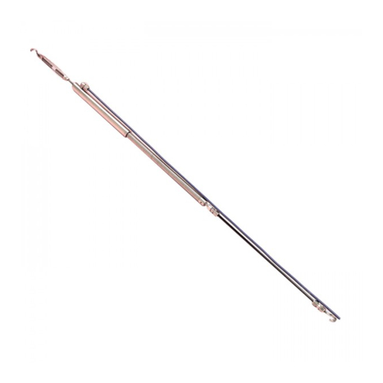
Model 4425
VW Convergence Meter
No part of this instruction manual may be reproduced, by any means, without the written consent of Geokon, Inc.
The information contained herein is believed to be accurate and reliable. However, Geokon, Inc. assumes no responsibility for
errors, omissions or misinterpretation. The information herein is subject to change without notification.
Copyright © 1985-2016 by Geokon, Inc.
(Doc Rev L, 11/10/16)
Advertisement
Table of Contents

Related Manuals for Geokon 4425


Summary of Contents for Geokon 4425
- Page 1 VW Convergence Meter No part of this instruction manual may be reproduced, by any means, without the written consent of Geokon, Inc. The information contained herein is believed to be accurate and reliable. However, Geokon, Inc. assumes no responsibility for errors, omissions or misinterpretation.
- Page 3 The buyer's sole remedy for any breach of this agreement by Geokon, Inc. or any breach of any warranty by Geokon, Inc. shall not exceed the purchase price paid by the purchaser to Geokon, Inc. for the unit or units, or equipment directly affected by such breach.
-
Page 5: Table Of Contents
ORRECTION FOR 4.5 E ........................13 NVIRONMENTAL ACTORS 5. TROUBLESHOOTING ..........................14 APPENDIX A - SPECIFICATIONS ....................... 15 A.1. M 4425 C ....................... 15 ODEL ONVERGENCE ETER A.2. T ) ...................... 15 HERMISTOR PPENDIX ALSO ... - Page 6 LIST of FIGURES, TABLES and EQUATIONS Page 1 - M 4425 C IGURE ODEL ONVERGENCE ETER ....................1 2 - M 4425 C IGURE ODEL ONVERGENCE ETER NSTALLATION ................ 2 3 - C IGURE ONVERGENCE ETER NSTALLATION...
-
Page 7: Introduction
Swagelok Fitting measured by the transducer. Thermistor The Model 4425 Convergence Meter consists of 3 Instrument Cable basic components. They are 1) the 2 anchor points, 2) 6 mm (¼") diameter connecting rods, and 3) the spring-tensioned vibrating wire transducer assembly. -
Page 8: Installation
Cement the eyebolt anchors in place using quick-set (hydraulic) cement or epoxy. Allow the cement or epoxy to set completely before attempting the installation of the convergence meter. Tunnel Cross Section Convergence Meter Connecting Rod Eyebolt Anchor Eyebolt Anchor Figure 2 - Model 4425 Convergence Meter Installation... - Page 9 Follow these steps to install the convergence meter; Attach the turnbuckle assembly to the convergence meter by screwing in the left-hand threaded portion. Use thread locking cement and tighten the lock nut. Set the turnbuckle such that about 10-12 mm (0.5") of thread is inside from each end. Measure the total distance from anchor eyebolt to anchor eyebolt, inside to inside at the points where they will touch the convergence meter eyehooks.
-
Page 10: Cable Installation
The instrument cables will pick up the 50 or 60 Hz (or other frequency) noise from the power cable and this will likely cause a problem obtaining a stable reading. Contact the factory concerning filtering options available for use with the Geokon dataloggers and readouts should difficulties arise. -
Page 11: Taking Readings
3. TAKING READINGS 3.1. Operation of the GK-403 Readout Box The GK-403 can store gage readings and also apply calibration factors to convert readings to engineering units, ie. inches or millimeters. Consult the GK-403 Instruction Manual for additional information on Mode "G" of the Readout. The following instructions will explain taking gage measurements using Mode "B". -
Page 12: Operation Of The Gk405 Readout Box
3.3 Operation of the GK405 Readout Box The GK-405 Vibrating Wire Readout is made up of two components: The Readout Unit, consisting of a Windows Mobile handheld PC running the GK-405 Vibrating Wire Readout Application The GK-405 Remote Module which is housed in a weather-proof enclosure and connects to the vibrating wire sensor by means of: 1) Flying leads with alligator type clips when the sensor cable terminates in bare wires or, 2) By means of a 10 pin connector.. -
Page 13: Data Reduction
4. DATA REDUCTION 4.1. Deformation Calculation The basic units utilized by Geokon for measurement and reduction of data from Vibrating Wire Convergence Meters are "digits". The units displayed by the all Readout Boxes in position "B" are digits. Calculation of digits is based on the following equation;... - Page 14 Figure 5 A typical Calibration Sheet...
-
Page 15: Temperature Correction
4.2. Temperature Correction The Model 4425 Vibrating Wire Convergence Meter has a very small coefficient of thermal expansion so in most cases correction is not necessary. However, if maximum accuracy is desired or the temperature changes are extreme (>10° C) corrections may be applied. The following equation applies;... -
Page 16: Rod Stretch Correction
All of the above thermal corrections describe an expansion of components with an increase in temperature. Hence, the calculated thermal corrections must be added to the deformation calculated using Equation 2. D tcorrected = D uncorrected + D temperature Equation 5 - Thermally Corrected Deformation Calculation Experience has shown that the most stable readings are obtained when the system is at a stable temperature. -
Page 17: Correction For Sag
Values for S are as follows: Range Spring Rate Model Number Inches lbs/in. Newtons/mm 4425-12 ½ 5.95 4425-25 5.95 4425-50 2.98 4425-100 2.98 4425-150 1.49 Table 4 – Spring Rates 4.4 Correction for Sag Correction for sag = - LW... - Page 18 D corrected = D uncorrected + D temperature + D rodstretch Equation 8 - Corrected Deformation Again, consider the following example from a Model 4425-12 Convergence Meter attached to 30 meters of ¼ inch diameter graphite rod. R 0 = 4919 digits R 1 = 6820 digits T 0 = 15.3°...
-
Page 19: Environmental Factors
From Equation 4 K = ((6820 0.000375) + 1.08) 0.002402 = 0.0087mm From Equation 2 D uncorrected = (6820 - 4919) 0.002402 = + 4.566 mm The plus sign indicates an extension From Equation 3 10 -6 ... -
Page 20: Troubleshooting
5. TROUBLESHOOTING Maintenance and troubleshooting of Geokon Vibrating Wire Convergence Meters are confined to periodic checks of cable connections and maintenance of terminals. The Convergence Meters contain no user-servicable components. However, consult the following list of problems and possible solutions should difficulties arise. Consult the factory for additional troubleshooting help. -
Page 21: Appendix A - Specifications
APPENDIX A - SPECIFICATIONS A.1. Model 4425 Convergence Meter Range: 12 mm 25 mm 50 mm 100 mm 150 mm 0.50 1 inch 2 inches 4 inches 6 inches inches 0.025% FSR Resolution:¹ 0.25% FSR Linearity: 0.1% FSR (with polynomial expression) Accuracy: <... -
Page 22: Appendix B - Thermistor Temperature Derivation
APPENDIX B - THERMISTOR TEMPERATURE DERIVATION Thermistor Type: YSI 44005, Dale #1C3001-B3, Alpha #13A3001-B3 Resistance to Temperature Equation: 273 2 A B LnR C LnR Equation B-1 Convert Thermistor Resistance to Temperature T Temperature in C. Where;... -
Page 23: Appendix C - Swagelok Fitting Assembly Instructions
APPENDIX C - SWAGELOK FITTING ASSEMBLY INSTRUCTIONS...
Need help?
Do you have a question about the 4425 and is the answer not in the manual?
Questions and answers