Table of Contents
Advertisement
Quick Links
Instruction Manual
Model 6300
Vibrating Wire In-Place Inclinometer
No part of this instruction manual may be reproduced, by any means, without the written consent of Geokon
.
®
The information contained herein is believed to be accurate and reliable. However, Geokon
®
assumes no responsibility for errors,
omissions or misinterpretation. The information herein is subject to change without notification.
Copyright © 1995-2019 by Geokon
®
(Doc Rev Q, 05/01/19)
Advertisement
Table of Contents

Related Manuals for Geokon 6300


Summary of Contents for Geokon 6300
- Page 1 Instruction Manual Model 6300 Vibrating Wire In-Place Inclinometer No part of this instruction manual may be reproduced, by any means, without the written consent of Geokon ® The information contained herein is believed to be accurate and reliable. However, Geokon ®...
- Page 3 Geokon or any breach of any warranty by Geokon shall not exceed the purchase price paid by the purchaser to Geokon for the unit or units, or equipment directly affected by such breach. Under no circumstances will Geokon reimburse the claimant for loss incurred in removing and/or reinstalling equipment.
-
Page 5: Table Of Contents
1.1 T ..........................2 ENSOR ONSTRUCTION 2. INSTALLATION ..............................3 2.1 P ............................3 RELIMINARY ESTS 2.2 M 6300 A ..................... 3 ODEL SSEMBLY AND NSTALLATION 2.2.1 Uniaxial System ............................4 2.2.2 Biaxial System ............................. 5 2.3 F ..............................7 LUID AMPING 2.4 S... - Page 6 FIGURES 1 - M 6300 T ......................1 IGURE ODEL ENSOR SSEMBLY 2 - M 6300 T .......................... 2 IGURE ODEL ENSOR 3 - T ..........................3 IGURE YPICAL NSTALLATION 4 - B ..................4 IGURE OTTOM HEEL SSEMBLY WITH...
-
Page 7: Introduction
1. INTRODUCTION The Geokon Model 6300 Vibrating Wire In-Place Inclinometer system is designed for long-term monitoring of deformations in structures such as dams, embankments, foundation walls and the like. The basic principle is the utilization of tilt sensors to make accurate measurement of inclination, over segments, in boreholes drilled into the structure being studied. -
Page 8: Tilt Sensor Construction
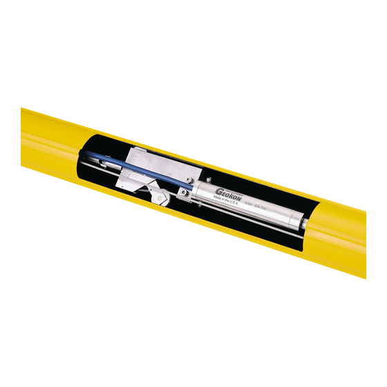
To prevent damage during shipment the tilt sensors are locked in place by means of a locking clamp screw. This slotted-head clamp screw must be removed and replaced by a Phillips-head seal screw, (provided in the zip-lock bag), to render the tiltmeter operative. Figure 2 - Model 6300 Tilt Sensor... -
Page 9: Installation
Table 2 in Appendix B. The resistance between any conductor and the shield should exceed two megohm. 2.2 Model 6300 Assembly and Installation 1) Connect the safety cable to the bottom wheel assembly. (See Figure 3.) This is strongly recommended. Not only... -
Page 10: Uniaxial System
Figure 4 - Bottom Wheel Assembly with Safety Cable 2) Connect the first length of gauge tubing to the bottom wheel assembly. The length of tube is shown in the table supplied with this manual. (In some cases, two tubes are joined together by a special union.) Use the 10-32 screws and nuts, and a thread locking cement to make this joint. -
Page 11: Biaxial System
2.2.2 Biaxial System The biaxial sensors are delivered unattached to the wheel assembly and to each other. The upper sensor should be attached to the wheel assembly using the two 10-32 nuts and cap screws supplied. The tongue of the sensor fits inside the slot of the wheel assembly with the orientation set such that the A+ direction marked on the sensor is aligned on the same side as the fixed wheel on the wheel assembly. -
Page 12: Figure 7 - Top Suspension
This assembly is now lowered into the borehole, using the safety cable, with the upper assembly fixed wheel aligned in the so-called A+ direction. It is customary (and recommended) to point the A+ direction in the same direction as the anticipated movement, i.e., towards the excavation being monitored or down-slope in the case of slope stability applications. -
Page 13: Fluid Damping
Contact Geokon for splicing materials and additional cable splicing instructions. Junction boxes and terminal boxes are available from Geokon for all types of applications. In addition, portable readout equipment and datalogging hardware are available. Contact Geokon... -
Page 14: Taking Readings
20 hours on two AA batteries. It is designed for the readout of all Geokon vibrating wire gauges and transducers; and is capable of displaying the reading in either digits, frequency (Hz), period (µs), or microstrain (µε). The GK-404 also displays the temperature of the transducer (embedded thermistor) with a resolution of 0.1 °C. -
Page 15: Gk-405 Readout Box
Connecting sensors with bare leads: Attach the GK-403-2 flying leads to the bare leads of a Geokon vibrating wire sensor by connecting each of the clips on the leads to the matching colors of the sensor conductors, with blue representing the shield (bare). -
Page 16: Gk-403 Readout Box (Obsolete Model)
Connecting Sensors with Bare Leads: Attach the GK-403-2 flying leads to the bare leads of a Geokon vibrating wire sensor by connecting each of the clips on the leads to the matching colors of the sensor conductors, with blue representing the shield (bare). -
Page 17: Data Reduction
4.1 Inclination Calculation Inclinations are measured in digits on Position B on the Geokon readout. The output of the VW tilt sensor is proportional to the sine of the angle of tilt. For small angles θ and sinθ are the same, so the relationship between output digits and the amount of tilting, (change of the angle of inclination), ∆θ, is given by the equation:... -
Page 18: Deflection Calculation
4.3 Deflection Calculation Now, the change in reading must be converted to a lateral deflection. The lateral deflection is defined as Lsin∆θ where L is the gauge length between pivot points and ∆θ is the change in inclination (corrected for temperature) determined from Equation 3. -
Page 19: Troubleshooting
5. TROUBLESHOOTING Maintenance and troubleshooting of the vibrating wire tilt sensors used in the Model 6300 Inclinometer are is confined to periodic checks of cable connections. The sensors are sealed and there are no user-serviceable parts. Consult the following list of problems and possible solutions should difficulties arise. Consult the factory for additional troubleshooting help. -
Page 20: Appendix A. Specifications
Electrical Cable: Two twisted pair (four conductor) 22 AWG Foil shield, PVC jacket, nominal OD=6.3 mm (0.250") Table 1 - Model 6300 Tilt Sensor Specifications Notes: ¹ Consult the factory for other ranges. ² Depends on readout equipment. With averaging techniques, it is possible to achieve one arc second ³... -
Page 21: Appendix B. Thermistor Temperature Derivation
APPENDIX B. THERMISTOR TEMPERATURE DERIVATION Thermistor Type: YSI 44005, Dale #1C3001-B3, Alpha #13A3001-B3 Resistance to Temperature Equation: A+B ( LnR ) +C(LnR) -273.15 °C Equation 5 - Resistance to Temperature Where; T = Temperature in °C. LnR = Natural Log of Thermistor Resistance A = 1.4051 ×... -
Page 22: Appendix C. Excitation And Readout Parameters
APPENDIX C. EXCITATION AND READOUT PARAMETERS The Micro-10 Datalogger which uses the Campbell Scientific Measurement and Control Module can be used to continuously monitor the Model 6300. The following parameters are recommended: C.1 Excitation The 2.5-volt excitation directly off the wiring panel is ideal for these sensors. The 5-volt supply from the AVW-1 and AVW-4 modules is also usable, but the 12-volt excitation should be avoided as it tends to overdrive the sensor. -
Page 23: Appendix D. Addressable Systems
The string of sensor is installed in a manner to that described in Section 2. The cable is connected, via a 15-pin connector, to a special Geokon Model 8021-1X datalogger modified, by the addition of a Model 8031 Distributed Multiplexer, specifically for use with the... -
Page 24: Appendix E. Typical Calibration Report
APPENDIX E. TYPICAL CALIBRATION REPORT Figure 11 - Sample Model 6300 Calibration Report...
Need help?
Do you have a question about the 6300 and is the answer not in the manual?
Questions and answers