Table of Contents
Advertisement
Quick Links
Installation Instructions
Model 6165
MEMS Tilt Beam
No part of this instruction manual may be reproduced, by any means, without the written consent of Geokon, Inc.
The information contained herein is believed to be accurate and reliable. However, Geokon, Inc. assumes no responsibility for
errors, omissions, or misinterpretation. The information herein is subject to change without notification.
Copyright © 2010-2018 by Geokon, Inc.
(Rev E, 07/17/18)
Advertisement
Table of Contents

Subscribe to Our Youtube Channel
Related Manuals for Geokon 6165


Summary of Contents for Geokon 6165
- Page 1 MEMS Tilt Beam No part of this instruction manual may be reproduced, by any means, without the written consent of Geokon, Inc. The information contained herein is believed to be accurate and reliable. However, Geokon, Inc. assumes no responsibility for errors, omissions, or misinterpretation.
- Page 3 Upon examination by Geokon, if the unit is found to be defective, it will be repaired or replaced at no charge. However, the WARRANTY is VOID if the unit shows evidence of having been tampered with...
-
Page 5: Table Of Contents
EMPERATURE ORRECTION 4.4 E ..........................8 NVIRONMENTAL ACTORS 5. TROUBLESHOOTING ............................9 APPENDIX A. SPECIFICATIONS ......................... 10 A.1 M 6165 MEMS T ........................10 ODEL A.2 T )......................10 HERMISTOR PPENDIX ALSO APPENDIX B. THERMISTOR TEMPERATURE DERIVATION ..............11 APPENDIX C. SAMPLE CALIBRATION REPORT ................... 12 APPENDIX D. - Page 6 FIGURES 1 - M 6165 MEMS T ......................... 1 IGURE ODEL 2 - B ..........................2 IGURE RACKET ARDWARE 3 - B ......................... 3 IGURE RACKETS TTACHED TO 4 - M ......................3 IGURE OUNTING RACKET RIENTATION 5 - M ..........................
-
Page 7: Introduction
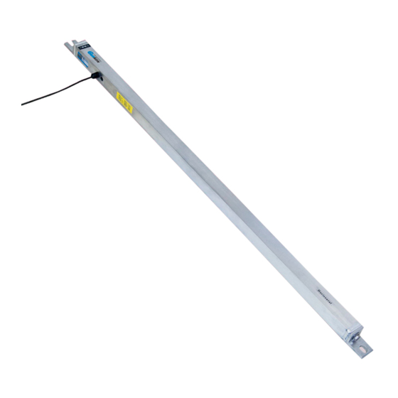
1. INTRODUCTION Geokon’s Model 6165 MEMS Tilt Beams are designed to be attached to structures, either vertically or horizontally, to measure any tilting or differential settlements that may occur. The tilt beams can be coupled together, in long horizontal strings, to measure differential settlement along embankments, railroad tracks, pipelines, tunnels, etc. -
Page 8: Installation
2. INSTALLATION 2.1 Preliminary Tests Prior to installation, each tilt beam should be checked for proper operation by completing the following: 1) Connect the beam to a readout or datalogger. (See Section 3 for readout and datalogger instructions.) 2) Depending upon which version of the tilt beam was purchased, hold the beam in a strictly horizontal or vertical position. -
Page 9: Mounting The Beam
Figure 3 - Brackets Attached to Beam Make sure the mounting brackets are orientated so that when the beam is mounted, the front of the beam will be facing out, as shown in Figure 4. Figure 4 - Mounting Bracket Orientation 2.3 Mounting the Beam 1) Place the beam in the desired location. -
Page 10: Figure 5 - Mounting Hardware
9) Attach the beam to the mounting surface by arranging the mounting hardware as shown in Figure 5. Use thread locking cement if desired. Figure 5 - Mounting Hardware 10) The beam must be level along the axis of the beam, as well as the perpendicular axis. This is to avoid any off-axis errors which can occur if the MEMS sensor is rotated axially too far away from a true horizontal or vertical position. -
Page 11: Taking Readings
In most cases, the tilt beam will be monitored continuously and automatically using a Datalogger. Connections to Geokon 8600 series dataloggers, which uses Campbell Scientific CR6 MCU are shown in Table 1 below. For further information, consult the 8600 Series Instruction Manual. -
Page 12: Measuring Temperature
See Section 4.3) The RB-500 will not read temperatures; a separate digital ohmmeter is required. (A Geokon GK-404 or GK-405 readout box can also be used; they have the ability to read the thermistor and display the temperature in degrees C.) -
Page 13: Data Reduction
R is the current reading in volts. is the reading at θ = zero. zero is the Gage Factor shown on the suppled calibration report (A typical 6165 calibration report tilt is shown in Appendix C.) Note that for measurements of tilt, i.e., changes of inclination, where R... -
Page 14: Temperature Correction
4.3 Temperature Correction The Model 6165 MEMS Tilt Beam sensor has negligible temperature sensitivity equal to one arc second per degree C or 0.0003 volts/ degree C. Tilt corrected for temperature = G ) - 0.0003(T )] degrees tilt Equation 4 - Temperature Correction - Tilt... -
Page 15: Troubleshooting
5. TROUBLESHOOTING Maintenance and troubleshooting of Model 6165 Tilt Beams are confined to periodic checks of the cable connections. The sensors are sealed and there are no user serviceable parts. Consult the following list of problems and possible solutions should difficulties arise. Consult the factory for additional troubleshooting help. -
Page 16: Appendix A. Specifications
Three twisted pair (Six conductor) 24 AWG for uniaxial Foil shield, PVC jacket, nominal OD = 6.3 mm Table 2 - Model 6165 MEMS Tilt Beam Sensor Specifications Notes: Depends on readout equipment. For best results requires a 4.5 digit digital voltmeter. -
Page 17: Appendix B. Thermistor Temperature Derivation
APPENDIX B. THERMISTOR TEMPERATURE DERIVATION Thermistor Type: YSI 44005, Dale #1C3001-B3, Alpha #13A3001-B3 Resistance to Temperature Equation: A+B ( LnR ) +C(LnR) -273.2 Equation 6 - Resistance to Temperature Where; T = Temperature in °C. LnR = Natural Log of Thermistor Resistance A = 1.4051 ×... -
Page 18: Appendix C. Sample Calibration Report
APPENDIX C. SAMPLE CALIBRATION REPORT Figure 6 - Sample Model 6165 Calibration Report... -
Page 19: Appendix D. Programming The Mems Tilt Beam With Crbasic
APPENDIX D. PROGRAMMING THE MEMS TILT BEAM WITH CRBASIC D.1 Description CRBASIC is the programming Language used with Campbell Scientific CRBASIC Dataloggers. Campbell’s Loggernet Software is typically used when programming in CRBASIC. The MEMS sensor should be read with the VoltDiff instruction and the output averaged 100x. No Thermistor in this example.
Need help?
Do you have a question about the 6165 and is the answer not in the manual?
Questions and answers