Table of Contents
Advertisement
Quick Links
Instruction Manual
Model 4000
(and 4050)
Vibrating Wire Strain Gage
No part of this instruction manual may be reproduced, by any means, without the written consent of Geokon, Inc.
The information contained herein is believed to be accurate and reliable. However, Geokon, Inc. assumes no responsibility for
errors, omissions or misinterpretation. The information herein is subject to change without notification.
1981, 1996, 2004, 2005, 2008, 2009, 2010, 2012, 2013, 2014, 2016
Copyright ©
by Geokon, Inc.
(Doc Rev Z, 8/16)
Advertisement
Table of Contents

Related Manuals for Geokon 4050


Summary of Contents for Geokon 4050
- Page 1 Vibrating Wire Strain Gage No part of this instruction manual may be reproduced, by any means, without the written consent of Geokon, Inc. The information contained herein is believed to be accurate and reliable. However, Geokon, Inc. assumes no responsibility for errors, omissions or misinterpretation.
- Page 3 The buyer's sole remedy for any breach of this agreement by Geokon, Inc. or any breach of any warranty by Geokon, Inc. shall not exceed the purchase price paid by the purchaser to Geokon, Inc. for the unit or units, or equipment directly affected by such breach.
-
Page 5: Table Of Contents
APPENDIX B - THEORY OF OPERATION .................... 19 APPENDIX C - THERMISTOR TEMPERATURE DERIVATION ............21 APPENDIX D - MODEL 4050 SPECIAL INSTRUCTIONS (12” GAGE LENGTH) ......22 APPENDIX E - MEASUREMENT OF, AND CORRECTION FOR, TEMPERATURE EFFECTS ... 23 ... - Page 6 LIST of FIGURES, TABLES and EQUATIONS 1 - M 4000 V IGURE ODEL IBRATING TRAIN ................1 2 - S IGURE PACING ..........................2 3 - W IGURE ELDING EQUENCE FOR THE OUNTING LOCKS ..............3 4 - T ...
-
Page 7: Introduction
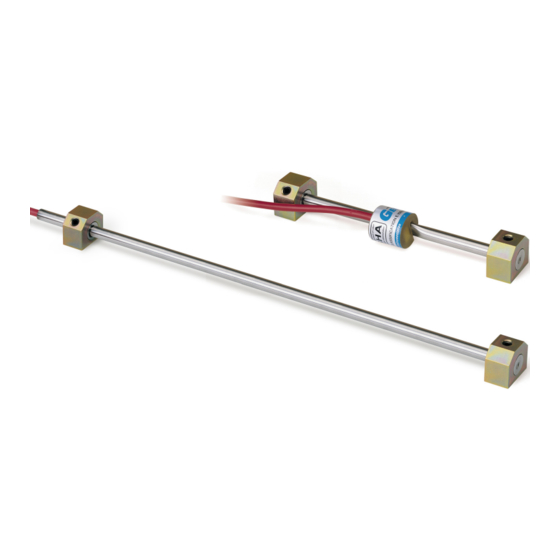
-1 - 1. INTRODUCTION The Geokon Model 4000 Vibrating Wire Strain Gage is intended primarily for long-term or short term strain measurements on structural steel members such as tunnel linings, arches, struts, piles, sheet piling, etc. The primary means of attachment is by conventional arc welding, but they may also be used to monitor strain changes on concrete or rock surfaces using anchors grouted into boreholes. -
Page 8: Gage Installation -General
2. GAGE INSTALLATION -GENERAL 2.1 Preliminary Tests A preliminary check is advisable, and this is made by placing the coil assembly onto the gage and connecting it to the GK-401, GK-402 or GK-403 Readout Box. Switch the position selector to "C" and turn the unit on. While gently pulling on the gage end blocks, observe the reading;... -
Page 9: Arc Welding Sequence
-3 - 2.3 Arc Welding Sequence The steel surface is cleaned using a wire brush to remove all scale, rust, dirt and oil. The blocks are then removed from the spacing jig and pressed firmly against the steel surface using the spacer bar as a handle. The edges of the mounting blocks are now welded in the order as shown in Figure 3. -
Page 10: Initial Readings
3.3 Protection from mechanical damage can be had by using the cover plates made by Geokon. (See Figure 4) Two 3/8 x 2 inch long hex-head bolts which will hold the cover plates should be welded in place hex-head down. The special cover plates are made from sheet steel formed into a channel shape. -
Page 11: Cable And Connector Protection
Conduit can be connected via conduit bulkhead connectors to the cover plates, (the Geokon cover plate has a knock-out which when punched out provides a hole for connecting the conduit connector), and to a readout enclosure. A typical readout enclosure has a hinged and gasketed cover that keeps the ends of the lead wires and/or plugs clean and dry. -
Page 12: Lightning Protection
Geokon provide locations for installation of these components. Lighting arrestor boards and enclosures are available from Geokon that install at the exit point of the instrument cable from the structure being monitored. The enclosure has a removable top so, in the event the protection board (LAB-3) is damaged, the user may service the components (or replace the board). -
Page 13: Gage Location
-7 - 4. GAGE LOCATION 4.1. End Effects If end effects are to be avoided then strain gages should be placed away from the ends of struts where they may be influenced by localized clamping or bolting distortions. For most structural members a distance of 5 feet is sufficient. - Page 14 Consider the example of an I-beam shown in Figure 6A. AX IS X X A XIS YY Figure 6A - Strain Gages Mounted on Central Web measures Axial Strain and Bending Moments about both XX and YY Axes Four strain gages (1, 2, 3 and 4) are welded in two pairs back to back on the central web. The gages are at a height (d) above the center of the web (axis yy) and at a distance (2c) apart.
- Page 15 -9 - Note that the total strain, at any point in the cross section, is the algebraic sum of the bending strains and the axial strain. It will be seen that the strains in the outer corners of the flange can be a lot higher than the strains measured on the web and that failure of the section can be initiated at these points, hence the importance of analyzing the bending moments.
- Page 16 This configuration has the advantage of positioning the gages and cables where they are easy to protect. In fact the cable from one gage can be passed through a hole drilled in the web so that both cables can be protected inside a single conduit. Another configuration of 2 gages that has been used is shown in figure 6D.
-
Page 17: Special Applications
-11 - 5. SPECIAL APPLICATIONS 5.1 Installation on Driven Steel Piles. Model 4000 strain gages, and their cables, mounted on steel piles need to be protected from being scraped off as the pile is driven into the ground. Protection is afforded by welding channels or angle iron over the top of the gages and cables as shown in the figure 7 below. -
Page 18: Installation On Steel Or Concrete Surfaces Using Epoxy Cements
5.2 Installation on Steel or Concrete Surfaces using Epoxy Cements. Geokon strain gages can be epoxied to steel or concrete surfaces if proper care is taken to clean the surfaces to be bonded and if sufficient time is allowed for the epoxy to cure before the gages are attached to the mounting blocks. -
Page 19: Installation On Concrete Surfaces Using Anchor Studs
5.875" 149 mm Figure 9 - Installation on Concrete using Groutable Anchors 6. TAKING READINGS The following three sections describe how to take readings using either of the two readouts available from Geokon. Model: 4000 4050 Readout Position: Display Units: digits (f 2 10 -3 ) -
Page 20: Operation Of The Gk-403 Readout Box
6.1. Operation of the GK-403 Readout Box The GK-403 can store gage readings and also apply calibration factors to convert readings to engineering units. Consult the GK-403 Instruction Manual for additional information on Mode "G" of the Readout. The GK-403 reads out the thermistor temperature directly in degrees C. -
Page 21: Operation Of The Gk-405 Readout Box
-15 - 6.3 Operation of the GK-405 Readout Box The GK-405 Vibrating Wire Readout is made up of two components: the Readout Unit, consisting of a Windows Mobile handheld PC running the GK-405 Vibrating Wire Readout Application the GK-405 Remote Module which is housed in a weather-proof enclosure and connects to the vibrating wire sensor by means of: 1) Flying leads with alligator type clips when the sensor cable terminates in bare wires or, 2) by means of a 10 pin connector.. -
Page 22: Data Interpretation
7. DATA INTERPRETATION Readings on Channel C of the GK-401, GK-403 or GK-404 Readout Box are displayed directly in microstrain based on the theoretical equation; 10 3 = 4.062 (f theory Where is the microstrain and f is the resonant frequency of the vibrating wire. 7.1 Conversion of the Readings to Strain Changes In practice the method of wire clamping effectively shortens the vibrating wire slightly causing it to over-register the strain. -
Page 23: Troubleshooting
-17 - Temperatures should be recorded at the time of each reading along with notes concerning the construction activity that is taking place. These data might supply logical reasons for observed changes in the readings. 8. TROUBLESHOOTING Maintenance and troubleshooting of Model 4000 Vibrating Wire Strain Gages are confined to periodic checks of cable connections and maintenance of terminals. -
Page 24: Appendix A - Specifications
APPENDIX A - SPECIFICATIONS Model 4000 Model 4050 3000 3000 Range (FS), (nominal): 1.0 1.0 Resolution: Accuracy Batch Calibration…+/- 0.5% FS Batch Calibration…+/- 0.5% FS Individual Calibration….+/- 0.1% Individual Calibration….+/- 0.1% Zero Stability: 0.02% FS/yr 0.02% FS/yr Linearity: +/- 0.5% FS... -
Page 25: Appendix B - Theory Of Operation
-19 - APPENDIX B - THEORY OF OPERATION A vibrating wire attached to the surface of a deforming body will deform in a like manner. The deformations alter the tension of the wire and hence also its natural frequency of vibration (resonance). - Page 26 6. Combining equations 4 and 5 gives: 7. Substituting the given values for , g and yields: 101142 8. On channel 'A', which displays the period of vibration, T, multiplied by a factor of 10 6 ; ...
-
Page 27: Appendix C - Thermistor Temperature Derivation
-21 - APPENDIX C - THERMISTOR TEMPERATURE DERIVATION Thermistor Type: YSI 44005, Dale #1C3001-B3, Alpha #13A3001-B3 Resistance to Temperature Equation: 273 2 A B LnR C LnR Equation C-1 Convert Thermistor Resistance to Temperature T Temperature in C. where: LnR ... -
Page 28: Appendix D - Model 4050 Special Instructions (12" Gage Length)
'V' groove. The Model 4050 is read on Channel B of the GK-401 and GK-403 Readouts. To set the gage for all-tension the reading should be approximately 2000; for all-compression, 10000; for mid-range set to 6000. Note: if a CR10 is being used the excitation range 1400 –... -
Page 29: Appendix E - Measurement Of, And Correction For, Temperature Effects
-23 - APPENDIX E - MEASUREMENT OF, AND CORRECTION FOR, TEMPERATURE EFFECTS If the ends of the structural member were free to expand or contract without restraint then strain changes would take place without any change in stress. And in these situations the strain gage would indeed show no change in reading. -
Page 30: Appendix F - Temperature Correction When Used On Concrete
APPENDIX F - TEMPERATURE CORRECTION WHEN USED ON CONCRETE In a free field, where no loads are acting, the thermal concrete strains are given by the following equation; ……………………………………….G1 thermal CF 2 represents the coefficient of expansion of concrete. Unless this figure is known, assume a nominal value of +10.4 microstrain/C. -
Page 31: Appendix G - Calculation Of Axial Loads And Bending Strains From Three Strain Gages, At 60 Degrees, On A Circular Pipe
-25 - APPENDIX G - CALCULATION OF AXIAL LOADS AND BENDING STRAINS FROM THREE STRAIN GAGES, AT 60 DEGREES, ON A CIRCULAR PIPE ε ε Θ θ ε ε + ε + ε Average Axial Strain ) /3 ε - ε Maximum Bending Strain around the YY Axis, (X) = +/- [ ( ) /1.732 ] ε... -
Page 32: Appendix H - Two Strain Gages Mounted One Above The Other
APPENDIX H - TWO STRAIN GAGES MOUNTED ONE ABOVE THE OTHER Where only one surface of the straining member is accessible then two strain gages can be used one mounted above the other, to separate axial strains from strains due to bending.
Need help?
Do you have a question about the 4050 and is the answer not in the manual?
Questions and answers