Table of Contents
Advertisement
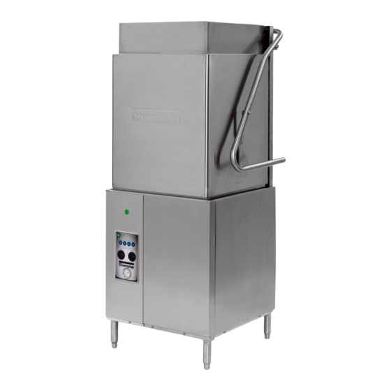
Tall Hood-type
Dishwashers
Installation, Operation, Cleaning and Maintenance Manual
LISTED
3765 Champion Boulevard
Winston-Salem, NC 27105
(336) 661-1556 Fax: (336) 661-1660
Toll-free: 1 (800) 858-4477
Issue Date: 2.24.16
Manual P/N
For machines beginning with S/N D150712934 and above
2674 N. Service Road, Jordan Station
Ontario, Canada L0R 1S0
(905) 562-4195 Fax: (905) 562-4618
Toll-free: 1( 800) 263-5798
M1.5 Series
Models:
DH5000T, MDHHD
Hot water sanitizing machine w/fresh
water rinse and built-in stainless steel
electric booster
Options:
Ventless Heat Recovery
115744 rev. B
Printed in the USA
Advertisement
Table of Contents

Related Manuals for Champion M1.5 Series


Summary of Contents for Champion M1.5 Series
- Page 1 Tall Hood-type Dishwashers Installation, Operation, Cleaning and Maintenance Manual M1.5 Series Models: DH5000T, MDHHD Hot water sanitizing machine w/fresh water rinse and built-in stainless steel electric booster Options: Ventless Heat Recovery Issue Date: 2.24.16 Manual P/N LISTED 115744 rev. B...
- Page 2 The USGBC and the CaGBC Member Logos are trademarks owned by the U.S. Green Building Council and The Canadian Green Building Council, respectively, and are used by permission. The logos signify only that Champion Industries, and Moyer Diebel are USGBC and a CaGBC members;...
- Page 3 Product Registration Three ways to REGISTER YOUR PRODUCT and ACTIVATE YOUR WARRANTY. 4:34 PM The QR website is an excellent resource for operators and service agents. • Use your mobile device to scan the QR code located on the front panel of your machine or enter our URL http://www.champdw.us/DH5000T.
- Page 4 Product Registration PRODUCT REGISTRATION BY FAX COMPLETE THIS FORM AND FAX TO: (336) 661-1660 in the USA 1-(800) 204-0109 in Canada PRODUCT REGISTRATION CARD Serial # Model Date of Installation: Company Name: Address: (Street) Province Postal Code Telephone #: ( Contact: Installation Company: Address:...
- Page 5 Revision History Revision History We reserve the right to make changes to this manual without notice and without incurring any liability by those changes. Equipment owners may request a revised manual, at no charge, by calling 1 (800) 858-4477 in the USA or by calling 1 (800) 263-5798 in Canada. Revision Revised Serial Number...
- Page 6 In the event that The Companies elect to repair, the labor and work to be performed in connection with the warranty shall be done during regular working hours by a Champion or Moyer Diebel authorized service technician.
-
Page 7: Table Of Contents
Table of Contents Table of Contents Revision History ........................ i Limited Warranty ......................ii Safety Symbols ........................iv Installation ..................1 Receiving and Placement ................1 Dish Table Connections ................2 Converting from Standard to Corner Operation ..........3 Water Connection ..................5 Standard Hot Water Connection ............ -
Page 8: Safety Symbols
Safety Symbols Safety Symbols The following symbols are used throughout this manual to alert the reader to important information. WARNING: Warnning statements indicate a condition or practice that can result in personal injury or possible death. CAUTION: Caution statements indicate a condition or practice that can result in damage to the machine or associated equipment. -
Page 9: Installation
Receiving and Placement - Installation Receiving Inspect the outside of the shipping carton for signs of damage and report any damage immediately to a supervisor. Remove the carton, inspect the dishwasher, and check the inside of the machine for accessories and installation parts. Register your machine by fax or online as soon as possible. -
Page 10: Dish Table Connections
Installation Dish Table Connections CAUTION: Dish tables should be secured to the dishwasher after it is permanently located. Dish table Dish table Fig. 2 - Standard straight-through operation. Refer to Fig. 3 below. 1. Level the dishwasher and dish tables to the required height. 2. -
Page 11: Converting From Standard To Corner Operation
Installation Converting from Standard to Corner Operation NOTE: An optional splash shield is available for corner operation but may not have shipped with the machine unless it was specified at the time of order. Contact the equipment dealer for instructions on how to order the splash shield. Refer to Fig. - Page 12 Installation Converting from Standard to Corner Operation (continued) Follow the steps below to convert the track assembly for corner operation: 1. Pull the track assembly straight up and lift it out of the machine, then rotate the track assembly 180° and reinstall it in the machine. 2.
-
Page 13: Water Connection
Installation Water Connection - Standard Model Connect the plumbing in accordance with the specifications below. WATER MINIMUM ¾” NPT HOT WATER SUPPLY LINE. CAUTION: To prevent damage to the dishwasher supply valves, the installing plumber must thoroughly flush debris from the water supply line before connecting it to the dishwasher. -
Page 14: Ventless Heat Recovery (Vhr) Cold Water Connection
Installation Water Connection - Ventless Heat Recovery (VHR) Model Connect the plumbing in accordance with the specifications below. COLD WATER MINIMUM ¾” NPT COLD WATER SUPPLY LINE. CAUTION: To prevent damage to the dishwasher supply valves, the installing plumber must thoroughly flush debris from the water supply line before connecting it to the dishwasher. -
Page 15: Drain Connection
Installation Drain Connection - Standard and VHR Models Connect the drain in accordance with the specifications below. DRAIN GRAVITY DRAIN - 2” OD SLIP-FIT HOSE CONNECTION. CAUTION: The dishwasher drain connection must comply with all local plumbing, health and safety codes. Damage caused by improper installation is not covered by the limited warranty AUTOMATIC ELECTRIC DRAIN VALVE. -
Page 16: Drain Water Tempering
Installation Water Connection for Drain Water Tempering Valve Standard and VHR Models NOTE: The drain water tempering kit is designed to reduce the temperture of water entering the building drain when the dishwasher is in the automatic drain cycle. A field installation kit is available from the factory if needed. Connect the plumbing in accordance with the specifications below. -
Page 17: Electrical Connections
Installation Electrical Connection - Single Phase and Three Phase Standard and VHR Models The installation of the dishwasher must comply with all local electrical, plumbing, health, and safety codes or in the absence of local codes, installed in accordance with the applicable requirements in the National Electrical Code, NFPA 70, Canadian Electrical Code (CEC), Part 1, CSA C22.1;... - Page 18 Installation Electrical Connection - Single Phase and Three Phase Standard and VHR Models (continued) Refer to the diagrams below for the main terminal block wiring and three phase and single phase motor connections. WARNING: There may be more than one power source connected to the machine.
-
Page 19: Ventilation Connection
Installation Ventilation - Vent Fan Control for Standard Model Only Standard model installations using an approved vent hood may require a vent fan signal. This signal is supplied by the dishwasher control circuit. A qualified installer must connect a signal circuit to the fuse holder and a common neutral terminal provided. -
Page 20: Chemical Connections
Installation Detergent Dispenser Connection - Standard and VHR Models USE A NON-CHLORINATED COMMERCIAL GRADE DETERGENT. WASH TANK CAPACITY: 9.5 US GAL / 7.9 IMP. GAL / 36 L TWO 7/8” DIAMETER HOLES ON LOWER RIGHT SIDE OF TANK. • TOP HOLE IS FOR DETERGENT INJECTION. •... - Page 21 Installation Rinse-Aid Dispenser Connection - Standard Model STD. RINSE / RACK: .85 US GAL / .7 IMP. GAL / 3.2 L R /A POT/PAN RINSE / RACK: 1.18 US GAL / .98 IMP. GAL / 4.5L 1/8” NPT PIPE PLUG AT THE REAR OF THE MACHINE NEAR THE VACUUM BREAKER FOR RINSE AID INJECTION.
-
Page 22: Operation
Operation Operation - Control Panel Description The control panel is located on the front left side of the lower panel. The controls include: A - ON/OFF green power button. Turns power on and off and initiates a drain cycle when the switch is placed in the OFF position. B - CYCLE green indicator light. - Page 23 Operation Control Panel Description CYCLE TIME WASH RINSE PRESSURE Fig. 21...
-
Page 24: Set-Up
Operation Operation - Set-up TURN WATER SUPPLY AND MAIN POWER ON. INSTALL PUMP STRAINER AND SCRAP SCREENS (See Fig. 22). INSTALL UPPER AND LOWER WASH AND RINSE SPRAY ARMS. MAKE SURE THEY SPIN FREELY (See Fig. 23). SCRAP SCREENS X 2 PUMP STRAINER Fig. -
Page 25: Loading Wares
Operation Operation - Loading Wares REMOVE LARGE FOOD PARTICLES AND DEBRIS BEFORE LOADING WARES. LOAD PLATES IN A PEG RACK, BOWLS AND GLASSES IN A FLAT-BOTTOM RACK. LOAD SILVERWARE IN A SINGLE LAYER IN A FLAT-BOTTOM RACK. LOAD POTS, PANS, AND UTENSILS UPSIDE DOWN IN A FLAT-BOTTOM RACK. LOAD BAKE SHEETS AND TRAYS ON THE SHORT EDGE IN A BAKE SHEET RACK. -
Page 26: Wash Cycles
Operation Operation - Wash Cycles NOTE: The DH5000T operates as a dishwasher in cycles 1 and 1.5 and as a pot/pan washer in cycles 4 and 5. CLOSE THE DOOR. PUSH THE POWER SWITCH ON. THE POWER SWITCH WILL ILLUMINATE. THE MACHINE WILL FILL WITH WATER AUTOMATICALLY. - Page 27 Operation Operation - Wash Cycles (continued) PRESS A BLUE TIME CYCLE BUTTON. THE BUTTON ILLUMINATES. CLOSE THE DOOR. THE GREEN CYCLE LIGHT ILLUMINATES AND THE WASH CYCLE BEGINS. THE WASH CYCLE IS FOLLOWED BY THE FINAL RINSE. CYCLE TIME Fig. 27 IF THE DOOR IS OPENED DURING A CYCLE, THE WASH TIMER WILL RESET AND THE DISHWASHER WILL RESTART THE CYCLE FROM THE BEGINNING.
-
Page 28: Rinse Sentry
Operation Operation - Wash Cycles (continued) MONITOR THE FINAL RINSE TEMPERATURE AND PRESSURE DURING THE FINAL RINSE. THE PRESSURE MUST BE A MINIMUM OF 20 PSI AND THE TEMPERATURE MUST BE A MINIMUM OF 180°F/82°C. 1 8 0 PRESSURE 20 PSI FINAL RINSE 180°F Fig. -
Page 29: Automatic Drain Cycle
Operation Operation - Automatic Drain Cycle The DH5000T is equiped with an automatic electrically operated drain valve. TO DRAIN THE DISHWASHER: OPEN THE DISHWASHER AND REMOVE ALL WARES FROM INSIDE THE MACHINE. PUSH THE POWER SWITCH OFF. THE POWER LIGHT WILL GO OUT. NOTE: THE GREEN CYCLE LIGHT IS OFF DURING THE DRAIN CYCLE. -
Page 30: Cleaning
Cleaning Cleaning WARNING: Dishwasher surfaces can be hot and cleaning chemicals can be caustic to the skin and eyes. Wear protective clothing and eye protection when handling chemicals and cleaning the machine. CLEAN THE MACHINE AT THE END OF EACH MEAL PERIOD OR AFTER EVERY 2 HOURS OF CONTINUOUS OPERATION AND AT THE END OF THE DAY. -
Page 31: Wash Tank And Scrap Screens
Cleaning Cleaning (continued) 5. Remove the scrap screens and pump strainer making sure that debris does not fall out of the screens and into the wash tank. Flush and backflush the screens in a sink. Do not strike the screens against hard surfaces. 6. -
Page 32: De-Lime
Cleaning Cleaning - Deliming Minerals accumulate on the interior surfaces of the dishwasher. The deposits have a white haze and, in cases of heavy accumulation, may appear as a granular solid. The generic name for mineral deposits is lime. The removal of lime deposits is called deliming. The dishwasher should be delimed regularly. -
Page 33: Maintenance
Maintenance Maintenance Daily Maintenance 1. Check all of the wash arm and rinse arm spray jets and clean as necessary. 2. Make sure the water supply is on and the drain is not clogged. 3. Check the temperature displays to ensure they are operating. 4. -
Page 34: Troubleshooting Chart
Maintenance Troubleshooting Condition Cause Solution Dishwasher will not run. Hood not closed. Close Hood completely. Main power OFF. Check breaker on panel. Dishwasher OFF. Turn dishwasher ON. Low or no water. Main water supply is off. Open supply valve. PRV setting incorrect. Set to 20-22 PSI flowing. -
Page 35: Temperature Display Error Codes
Maintenance Troubleshooting - Display Error Codes Indicates the wash thermistor is defective. Indicates the final rinse thermistor is defective. Indicates the booster thermistor is defective. - Page 36 Blank Page This Page Intentionally Left Blank...
-
Page 37: Timing Charts And Electrical Schematic
Time Cycle Chart TIME CYCLE - Tall Hood-type Series - MODE "B" DRAWING REPRESENTS ONLY THE STRUCTURE OF TIME CYCLES. FOR MODES OF OPERATION SEE DWG# 114470 SHEETS 10-16 NORMAL CYCLE EXTENDED CYCLE 60 SECONDS TOTAL CYCLE 90 SECONDS TOTAL CYCLE WASH 35 SECONDS WASH... - Page 38 Time Cycle Chart NOTES: JUMPER SETTINGS: TRIGGERING EVENT: JB1 = OPEN JB2 = CLOSED CYCLE SWITCH IN POSITION 1, 2, 3 OR Tall Hood-type Series - MODE C - TIME CYCLES 3 AND 4 JB3 = OPEN "CYCLE SWITCH" STATE IS IGNORED DRAWING REPRESENTS ONLY THE STRUCTURE OF TIME CYCLES 3 AND 4.
-
Page 39: Electrical Schematic
Tall Hood-type PLC Electrical Schematic... - Page 40 Blank Page This Page Intentionally Left Blank...
Need help?
Do you have a question about the M1.5 Series and is the answer not in the manual?
Questions and answers