
Subscribe to Our Youtube Channel
Related Manuals for Invertek Compact 2 Series


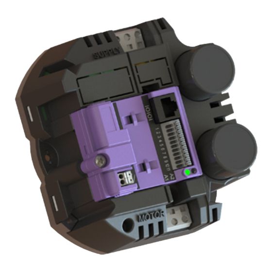
Summary of Contents for Invertek Compact 2 Series
- Page 1 Optidrive Compact-2 Engineering Guide Issue 07.docx User Guide Compact 2 AC Variable Speed Drive 0.37 – 4.0kW (0.5 – 5HP) 230V-480V Engineering Guide www.invertekdrives.com...
-
Page 2: Table Of Contents
Optidrive Compact-2 Engineering Guide Issue 07.docx About this Advanced Technical Manual ..........................5 1.1. Compatibility 1.2. Intended Audience Important Safety Information ..............................6 Product Overview .................................. 7 3.1. General Information 3.2. Model Code Definition 3.3. Available Models 3.4. Power Module Output Current Capacity Mechanical Information and Mounting .......................... - Page 3 Optidrive Compact-2 Engineering Guide Issue 07.docx 11.9. Automatic Switching Frequency Reduction 11.10. Electrical Rating Tables Diagnostic & Status Information ............................51 12.1. Status Indication LEDs 12.2. Fault Code Messages Appendices ..................................52 13.1. Appendix A – Disconnecting the EMC Filter Revision History ................................
- Page 4 Engineering Guide Issue 07 (05/18) Invertek Drives Ltd adopts a policy of continuous improvement and whilst every effort has been made to provide accurate and up to date information, the information contained in this User Guide should be used for guidance purposes only and does not form the part of any contract.
-
Page 5: About This Advanced Technical Manual
This Document is for use with version 2.02 Firmware. Invertek Drives Ltd adopts a policy of continuous improvement and whilst every effort has been made to provide accurate and up to date information, the information contained in this User Guide should be used for guidance purposes only and does not form the part of any contract. -
Page 6: Important Safety Information
Ensure that all terminals are tightened to the appropriate torque setting Do not attempt to carry out any repair of the Compact 2. In the case of suspected fault or malfunction, contact your local Invertek Drives Sales Partner for further assistance. www.invertekdrives.com... -
Page 7: Product Overview
Optidrive Compact-2 Engineering Guide Issue 07.docx 3. Product Overview 3.1. General Information The Optidrive Compact 2 is a dedicated range of products intended for integration directly into a machine design. All units consist of a base Power Module (PM) and Control Module (CM) which, when combined together become a complete drive unit. This construction method provides enhanced flexibility. -
Page 8: Available Models
Optidrive Compact-2 Engineering Guide Issue 07.docx 3.3. Available Models 3.3.1. Standard Units 110 – 115 + 10% / - 10%, 1 Phase Input, 3 Phase 230V Output (Voltage Doubler) Output Output Output Frame Brake Model Code - Filtered Model Code - Unfiltered Voltage Phases Current... -
Page 9: Mechanical Information And Mounting
Optidrive Compact-2 Engineering Guide Issue 07.docx 4. Mechanical Information and Mounting 4.1. General Compact 2 Power Modules must be mounted onto a suitable flat metallic surface with sufficiently low thermal resistance to allow dissipation of the heat produced. Surface flatness must be =<+ / - 0.2mm over the mounting area ... - Page 10 Optidrive Compact-2 Engineering Guide Issue 07.docx 4.2.2. Frame Size 1C –PFC Drives Overall Dimensions Mounting Points Depth : Use 3 x M4 (No. 8) bolts or screws, tightening torque : 4Nm / 3ft-lb Weight 0.7kg, 1.54lb 4.2.3. Frame Size 2 Overall Dimensions Mounting Points Depth : 89mm...
-
Page 11: Removing/Changing The Control Module
Optidrive Compact-2 Engineering Guide Issue 07.docx 4.3. Removing/Changing the Control Module. Control Module removal. Fully unscrew the cross head screw. Press finger grips and Lift the Control module from the screw side. Rotate towards the control terminal side as shown. 4.4. -
Page 12: Typical Heatsink Requirement
Optidrive Compact-2 Engineering Guide Issue 07.docx 4.6. Typical Heatsink Requirement The table below provides typical values for heatsink thermal resistance. 4.6.1. Single Phase Input 110 – 115VAC Supply Models Base Unit Effective Typical Approximate Maximum Recommended Model Switching Rated Efficiency Heatsink Maximum Code... - Page 13 Optidrive Compact-2 Engineering Guide Issue 07.docx 4.6.4. Three Phase Input 380 – 480VAC Supply Models Base Unit Effective Typical Approximate Maximum Recommended Model Switching Rated Efficiency Heatsink Maximum Code Frequency Output Temperature Heatsink (KHz) Power (ᵒC) Thermal Resistance (K/W) OPC-2-140022-3#10003E 97.7% 97.3% 96.8%...
-
Page 14: Electrical Power Wiring And Installation
Optidrive Compact-2 Engineering Guide Issue 07.docx 5. Electrical Power Wiring and Installation 5.1. Connection Diagram Ensure there is at least 30 seconds between each power-on. Isolator Install suitably rated fuses/Circuit breakers . If an earth leakage detection device is used (e.g.ELCB/RCD), a type Fuses / Fuse / Circuit Breaker Selection Circuit... -
Page 15: Protective Earth (Pe) Connection
Optidrive Compact-2 Engineering Guide Issue 07.docx 5.2. Protective Earth (PE) Connection Grounding Guidelines The ground terminal of each Optidrive should be individually connected DIRECTLY to the site ground bus bar (through the filter if installed). Optidrive ground connections should not loop from one drive to another, or to, or from any other equipment. ... -
Page 16: Motor Connection
Optidrive Compact-2 Engineering Guide Issue 07.docx 5.3.2. Fuse / Circuit Breaker Selection Suitable fuses to provide wiring protection of the input power cable should be installed in the incoming supply line, according to the data in section 11.10 Electrical Rating Tables on page 50. The fuses must comply with any local codes or regulations in place. In general, type gG (IEC 60269) or UL type J fuses are suitable;... -
Page 17: Control Wiring
Optidrive Compact-2 Engineering Guide Issue 07.docx 6. Control Wiring 6.1. Control Terminal Wiring All analog signals should be connected using suitably shielded, twisted pair cables. Power and Control Signal cables should be routed separately where possible, and must not be routed parallel to each other. ... -
Page 18: Parameter Set Overview
Optidrive Compact-2 Engineering Guide Issue 07.docx 7. Parameter Set Overview 7.1. About this section This document provides a list of the available parameters, and a description of their respective functions, for the Optidrive Compact. Access to the parameters requires one of the following ... -
Page 19: Parameter Descriptions
Optidrive Compact-2 Engineering Guide Issue 07.docx 7.4. Parameter Descriptions 7.4.1. Basic Parameters Par. Description Minimum Maximum Default Units P-01 Maximum Frequency / Speed Limit P-02 500.0 50.0 (60.0) Hz / RPM Maximum output frequency or motor speed limit set in Hz or RPM. The maximum possible value is limited by the lower of the following :- 500.0Hz maximum limit If P-10 >0, (500 x 120) / Motor Poles RPM... - Page 20 Control via CAN (RS485) interface with Accel / Decel ramps updated via CAN Slave Mode Control via a connected Invertek drive in Master Mode. Slave drive address must be > 1. NOTE When P-12 = 1, 2, 3, 4, 7, 8 or 9, an enable signal must still be provided at the control terminals, digital input 1...
- Page 21 Optidrive Compact-2 Engineering Guide Issue 07.docx 7.4.2. Extended parameters Par. Description Minimum Maximum Default Units P-15 Digital Input Function Select Defines the function of the digital inputs depending on the control mode setting in P-12. See section 8 Control Terminal Connections for more information.
- Page 22 Optidrive Compact-2 Engineering Guide Issue 07.docx Par. Description Minimum Maximum Default Units Load Current (Torque) 0 – 200.0% of P-08, updated every 64ms P-26 Skip frequency hysteresis band P-01 Hz / RPM P-27 Skip Frequency Centre Point P-01 Hz / RPM The Skip Frequency function is used to avoid the Optidrive operating at a certain output frequency, for example at a frequency which causes mechanical resonance in a particular machine.
- Page 23 Optidrive Compact-2 Engineering Guide Issue 07.docx Par. Description Minimum Maximum Default Units P-33 Spin Start (S2 & S3 Only) / DC Injection Time On Start (S1 Only) Setting Function Description Disabled Enabled When enabled, on start up the drive will attempt to determine if the motor is already rotating, and will begin to control the motor from its current speed.
- Page 24 Optidrive Compact-2 Engineering Guide Issue 07.docx Par. Description Minimum Maximum Default Units P-43 PI Controller Operating Mode Setting Function Description Direct Operation Use this mode if when the feedback signal drops, the motor speed should increase. When the drive restarts following standby, the PID controller will restart from zero. Inverse Operation Use this mode if when the feedback signal drops, the motor speed should decrease.
- Page 25 Optidrive Compact-2 Engineering Guide Issue 07.docx 7.4.3. Advanced Parameters Par. Description Minimum Maximum Default Units P-51 Motor Control Mode Setting Control Method Vector speed control mode for Induction Motors V/f mode for Induction Motors PM vector speed control for Permanent Magnet Motors BLDC vector speed control for Brushless DC Motors SR vector speed control for Synchronous Reluctance Motors LSPM vector speed control for Line Start Permanent Magnet Motors...
-
Page 26: Parameter Group 0 – Monitoring Parameters (Read Only)
Optidrive Compact-2 Engineering Guide Issue 07.docx 7.5. Parameter Group 0 – Monitoring Parameters (Read Only) Par. Description Explanation P00-01 1 Analog input value (%) 100% = max input voltage P00-02 2 Analog input value (%) 100% = max input voltage P00-03 Speed reference input (Hz / RPM) Displayed in Hz if P-10 = 0, otherwise RPM P00-04 Digital input status... -
Page 27: Control Terminal Connections
Optidrive Compact-2 Engineering Guide Issue 07.docx 8. Control Terminal Connections For standard applications and operation, the basic control of the drive and functions of all drive input terminals can be configured using just two parameters, P-12 and P-15. P-12 is used to define the source of all control commands and the primary speed reference source. P-15 then allows fast selection of Analog and Digital Input functions based on a selection table. -
Page 28: Overview
Optidrive Compact-2 Engineering Guide Issue 07.docx 8.2. Overview Optidrive Compact 2 uses a Macro approach to simplify the configuration of the Analog and Digital Inputs. There are two key parameters which determine the input functions and drive behaviour:- P-12 – Selects the main drive control source and determines how the output frequency of the drive is primarily controlled. ... - Page 29 Optidrive Compact-2 Engineering Guide Issue 07.docx 8.3.1. Macro Functions – Terminal Mode (P-12 = 0) P-15 DI3 / AI2 DI4 / AI1 Diagram FWD REV STOP AI1 REF P-20 REF Analog Input AI1 STOP AI1 REF PR-REF P-20 P-21 Analog Input AI1 STOP...
- Page 30 Optidrive Compact-2 Engineering Guide Issue 07.docx 8.3.2. Macro Functions - Keypad Mode (P-12 = 1 or 2) P-15 DI3 / AI2 DI4 / AI1 Diagram INC SPD DEC SPD FWD REV STOP ENABLE ˄------------------ START -----------------˄ STOP ENABLE PI REF...
- Page 31 Optidrive Compact-2 Engineering Guide Issue 07.docx 8.3.3. Macro Functions - Fieldbus Control Mode (P-12 = 3, 4, 7, 8 or 9) P-15 DI3 / AI2 DI4 / AI1 Diagram STOP ENABLE FB REF (Fieldbus Speed Reference, Modbus RTU / CAN / Master-Slave defined by P-12) STOP ENABLE PI REF...
- Page 32 Optidrive Compact-2 Engineering Guide Issue 07.docx 8.3.4. Macro Functions - User PI Control Mode (P-12 = 5 or 6) P-15 DI3 / AI2 DI4 / AI1 Diagram STOP ENABLE PI REF P-20 REF Analog Input AI2 Analog Input AI1 STOP ENABLE PI REF AI1 REF...
-
Page 33: Example Connection Diagrams
Optidrive Compact-2 Engineering Guide Issue 07.docx 8.4. Example Connection Diagrams Diagram 1 Diagram 2 Diagram 3 Diagram 4 P-16 = 0 – 10V, (NC) P-16 = 0 – 10V P-47 = 0 – 10V, P-16 = 0 – 4- 20mA, etc. 4- 20mA, etc. -
Page 34: Software Functions
Optidrive Compact 2 includes an embedded function to allow the user to create their own “default” parameters. This means that if a factory reset is carried out, the drive will return to these parameters, as opposed to the Invertek Drive factory default parameters. - Page 35 Optidrive Compact-2 Engineering Guide Issue 07.docx Make any changes to the parameter set as required. Changes from Invertek factory default settings are highlighted in blue. In the File menu, select “Save Current Parameters as User Defaults in Drive” www.invertekdrives.com...
- Page 36 Optidrive Compact-2 Engineering Guide Issue 07.docx The confirmation message will appear. Clearing User Default Parameters In order to clear the User Default parameters, the following method is used. From the File menu, select “Clear User Default Parameters in Drive” www.invertekdrives.com...
- Page 37 Optidrive Compact-2 Engineering Guide Issue 07.docx The confirmation message will appear to show the user defaults are now cleared, and resetting the drive will return it to Invertek Drives Factory default settings. www.invertekdrives.com...
-
Page 38: Serial Communications
Optidrive Compact-2 Engineering Guide Issue 07.docx 9. Serial Communications 9.1. Overview OPC-2-CON-E-IN provides support for the following fieldbus networks and functions:- Fieldbus Interface Availability Drive Control Drive Parameter Access Modbus RTU On-board RJ45 From Launch Access to all Writable Parameters CAN bus On-board RJ45 From Launch... - Page 39 Optidrive Compact-2 Engineering Guide Issue 07.docx 9.3.1. PDO Default Mapping Objects Mapped Length Mapped Function Transmission Type Object 2000h Unsigned 16 Control command register 2001h Integer 16 Speed reference PDO1 Valid immediately 2003h Unsigned 16 User ramp reference 0006h Unsigned 16 Dummy 200Ah Unsigned 16...
- Page 40 Optidrive Compact-2 Engineering Guide Issue 07.docx 9.3.3. CAN Specific Object Table Index Function Access Type Default Value Index 1000h Device Type 1001h Error Register 1002h Manufacturer Status Register 1005h COB-ID Sync 00000080h 1008h Manufacturer Device Name String 1009h Manufacturer Hardware Version String x.xx 100Ah...
- Page 41 Optidrive Compact-2 Engineering Guide Issue 07.docx 9.3.4. Parameter Access Overview The accessible parameter numbers and respective scaling are listed in the following tables. The method to access the parameters depends on the fieldbus type in use as described in the following section. The R/W column indicates whether the values are Writeable as well as readable (R/W) or Read Only (R) The data types for the parameter are defined as follows:- WORD...
- Page 42 Optidrive Compact-2 Engineering Guide Issue 07.docx Modbus Parameter Upper byte Lower Byte Format Type Scaling Open Index Number Register Index 26D7h P00-13 Trip 1 Time - Seconds 3599 100 = 100 Seconds 27D8h P00-13 Trip 2 Time – Hours 65535 1 = 1 Hour 27D9h P00-13...
- Page 43 Optidrive Compact-2 Engineering Guide Issue 07.docx 9.3.6. Modbus RTU / CAN Index – Parameters Modbus Open Par. Description Format Data format / scaling Register Index 2065h Max speed limit 5*P-09 Internal value (3000 = 50.0Hz) 2066h Min speed limit P-01 Internal value (3000 = 50.0Hz) 2067h Accel ramp time...
- Page 44 Optidrive Compact-2 Engineering Guide Issue 07.docx Modbus Open Par. Description Format Data format / scaling Register Index 2097h Motor Control Mode See parameter description for details 2098h Motor Parameter Autotune 2099h Vector Mode Gain 2000 1dp, e.g. 500 = 50.0% 209Ah Maximum Current Limit 1750...
- Page 45 Optidrive Compact-2 Engineering Guide Issue 07.docx Modbus RTU Registers 25 - 28: Drive Serial Number The drive serial number may be read using these four registers. The serial number has 11 digits, stored as follows:- Register 28 Register 27 Register 26 Register 25 e.g.
- Page 46 Optidrive Compact-2 Engineering Guide Issue 07.docx Motor Overload Configuration (P-60) This parameter is stored as follows :- High Byte Low Byte Reserved I x t Reaction 0: It.trp 1: Current Limit Reduction UL Thermal Overload Retention 0: Disabled 1: Enabled 9.3.8.
-
Page 47: Additional Options
Optidrive Compact-2 Engineering Guide Issue 07.docx Additional Options 10.1. Managing the remote Keypad. The drive is configured and its operation monitored via the keypad and display. Used to display real-time information, to access and exit NAVIGATE parameter edit mode and to store parameter changes Used to increase speed in real-time mode or to increase parameter values in parameter edit mode Used to decrease speed in real-time mode or to decrease... -
Page 48: Technical Data
Optidrive Compact-2 Engineering Guide Issue 07.docx Technical Data 11.1. Environmental Operational ambient temperature range : -10 … 50°C (frost and condensation free) Storage ambient temperature range : -40 … 60°C Maximum altitude : 2000m. Derate above 1000m: 1% / 100m Maximum humidity : 95%, non-condensing 11.2. -
Page 49: Response Times
Optidrive Compact-2 Engineering Guide Issue 07.docx 11.5. Response Times Command Source Response Time Digital Input <8ms Analog Input <16ms Modbus RTU Interface <8ms From receipt of valid command CAN Interface <8ms From receipt of valid command Master / Slave Function <8ms, response, 60ms cycle Power Stage <10ms to enable output... -
Page 50: Under / Over Voltage Trip Levels
Optidrive Compact-2 Engineering Guide Issue 07.docx 11.8. Under / Over Voltage Trip Levels The following levels are not user adjustable, and define the operating voltage levels of the drive and brake chopper circuit. Drive Rated Frame Drive Type DC Bus Voltage Level (Volts DC) Supply Voltage Size Brake... - Page 51 Optidrive Compact-2 Engineering Guide Issue 07.docx Diagnostic & Status Information 12.1. Status Indication LEDs Each control module features two status LED’s, labelled A1 and A2; these indicate the drive status as follows. 12.1.1. LED A1 indication This LED has three colours, and indicates the drive status as follows:- LED Status Drive Status Green...
- Page 52 Optidrive Compact-2 Engineering Guide Issue 07.docx Appendices 13.1. Appendix A – Disconnecting the EMC Filter Remove the screws highlighted below. Frame Size 1A and 1B Frame Size 1C Frame Size 2 www.invertekdrives.com...
- Page 53 Optidrive Compact-2 Engineering Guide Issue 07.docx Revision History Issue Note Section Date Pre Release 05/01/16 Firmware version number added 15/11/16 Revision number updated Changed description of mounting surface Revised power module part numbers Added PFC unit mounting and dimensions 4.2.2 Added section relating to operating with Hz / RPM 7.3.1 Ambient temperature limit raised to 50ᵒC...
Need help?
Do you have a question about the Compact 2 Series and is the answer not in the manual?
Questions and answers