Microsemi IGLOO2 FPGA DSP FIR Filter Demo Manual
Libero soc v11.7
Hide thumbs
Also See for IGLOO2 FPGA DSP FIR Filter:
- Application note (102 pages) ,
- User manual (64 pages) ,
- Manual (15 pages)
Table of Contents
Advertisement
Quick Links
Advertisement
Table of Contents

Subscribe to Our Youtube Channel
Related Manuals for Microsemi IGLOO2 FPGA DSP FIR Filter


Summary of Contents for Microsemi IGLOO2 FPGA DSP FIR Filter
- Page 1 IGLOO2 FPGA DSP FIR Filter - Libero SoC v11.7 DG0504 Demo Guide...
-
Page 2: Table Of Contents
2 IGLOO2 FPGA DSP FIR Filter ........ - Page 3 Figures Figure 1. Top-Level Diagram of DSP FIR Filter Demo ......... . . 6 Figure 2.
- Page 4 Tables Table 1. Design Requirements ............7 Table 2.
-
Page 5: Preface
UG0450: SmartFusion2 SoC FPGA and IGLOO2 FPGA System Controller User Guide • UG0448: IGLOO2 FPGA High Performance Memory Subsystem User Guide Refer to the following web page for a complete and up-to-date listing of IGLOO2 device documenta- tion: http://www.microsemi.com/products/fpga-soc/fpga/igloo2docs. Revision 6... -
Page 6: Igloo2 Fpga Dsp Fir Filter
(pass-band frequency and stop-band frequency), and also plots the input or output waveforms, and the required spectrum. Microsemi CoreFIR filter IP is used to suppress the unwanted frequency components, and CoreFFT IP is used to generate the output spectrum to verify the filtering operation. -
Page 7: Design Requirements
USB to UART drivers Framework Microsoft .NET Framework 4 Client for launching demo GUI Demo Design 2.3.1 Introduction The design files are available for download from the following path in the Microsemi website: http://soc.microsemi.com/download/rsc/?f=m2gl_dg0504_dsp_fir_filter_liberov11p7_df The design files include: • Design Files •... -
Page 8: Demo Design Description
IGLOO2 FPGA DSP FIR Filter 2.3.2 Demo Design Description This demo design uses the following blocks: • Data Handle (user RTL) • Filter Control (user RTL) • TPSRAM IP (IPcore) • CoreUART(IPcore) • CoreFIR (IPcore) • CoreFFT (IPcore) • SYSRESET (IPcore) •... -
Page 9: Tpsram Ip
IGLOO2 FPGA DSP FIR Filter 2.3.2.3 TPSRAM IP TPSRAM IP uses the following configurations: • Filter coefficient buffer • Input signal data buffer • Output signal buffer • Output signal FFT real data buffer • Output signal FFT imaginary data buffer Table 2 •... -
Page 10: Sysreset
IGLOO2 FPGA DSP FIR Filter 2.3.2.7 SYSRESET The SYSRESET IP provides the power on reset signal. 2.3.2.8 OSC The OSC IP is configured as an RC oscillator to provide the 50 MHz signal to the clock conditioning circuit (CCC). 2.3.2.9 CCC The CCC IP is configured to provide a 150 MHz clock signal. -
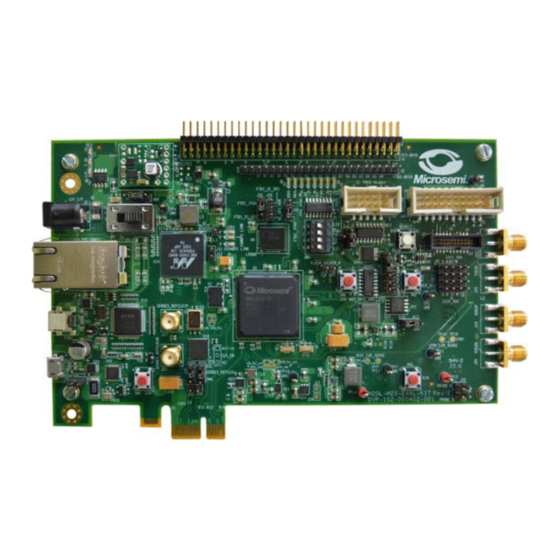
Page 11: Figure 4. Igloo2 Evaluation Kit Dsp Fir Filter Demo Setup
IGLOO2 FPGA DSP FIR Filter Figure 4 shows the board setup for running the DSP FIR Filter demo on the IGLOO2 Evaluation Kit. Figure 4 • IGLOO2 Evaluation Kit DSP FIR Filter Demo Setup Revision 6... -
Page 12: Figure 5. Usb To Uart Bridge Drivers
IGLOO2 FPGA DSP FIR Filter Ensure that the USB to UART bridge drivers are automatically detected. This can be verified in the Device Manager of the host PC. The FTDI USB to UART converter enumerates four COM ports. For USB 2.0, note down the USB Serial Converter D COM port number to use it in the Figure 5 shows the USB 2.0 Serial port properties and the connected... -
Page 13: Programming The Demo Design
IGLOO2 FPGA DSP FIR Filter Programming the Demo Design The following steps describe how to program the demo design: Download the demo design from: http://soc.microsemi.com/download/rsc/?f=m2gl_dg0504_dsp_fir_filter_liberov11p7_df Switch ON the power supply switch, SW7. Launch the FlashPro software. Click New Project. In the New Project window, enter the project name as IGL2_FIR_FILTER. -
Page 14: Setting Up The Device
IGLOO2 FPGA DSP FIR Filter 2.5.1 Setting Up the Device The following steps describe how to configure the device: Click Configure Device on the FlashPro GUI. Click Browse and navigate to the location where the IGL2_FIR_FILTER.stp file is located and select the file. -
Page 15: Figure 8. Flashpro Project Run Passed
IGLOO2 FPGA DSP FIR Filter Click PROGRAM to start programming the device. Wait until Programmer Status is changed to RUN PASSED. Figure 8 • FlashPro Project RUN Passed Revision 6... -
Page 16: Dsp Fir Demo Gui
IGLOO2 FPGA DSP FIR Filter 2.5.3 DSP FIR Demo GUI The DSP FIR demo is provided with a user-friendly GUI that runs on the host PC which communicates with the IGLOO2 Evaluation Kit. The UART is used as the underlying communication protocol between the host PC and IGLOO2 Evaluation Kit. -
Page 17: Running The Demo Design
IGLOO2 FPGA DSP FIR Filter Running the Demo Design The following steps describe how to run the demo design: Launch the DSP FIR Demo GUI executable file available in the design files. (\IGL2_FIR_FILTER_DF\GUI\IGL2_FIR_Filter.exe). The FIR Filter Demo window is displayed, as... -
Page 18: Figure 11. Filter Generation - 1
IGLOO2 FPGA DSP FIR Filter Filter Generation: Two options are provided for generating the filter coefficients: • Generate the coefficients using MATLAB or any similar tool and save it as a text file (Refer to "Appendix: Coefficient Text File Format" on page 32 for the format of the text file). -
Page 19: Figure 12. Filter Generation - 2
IGLOO2 FPGA DSP FIR Filter • Generate the Filter coefficients using the GUI. The following parameters are required to generate filter coefficients: • Filter Type: Low-pass (Low-pass/High-pass/Band-pass/Band-reject filter) • Filter Window: Blackman (Blackman/Hamming window) • Low Cut-off Frequency: Disabled for Low-pass filter required (high cut-off frequency is disabled for high-pass filter) •... -
Page 20: Figure 13. Filter Response And Filter Coefficient Plot
IGLOO2 FPGA DSP FIR Filter The successful after-generation graphs of the filter coefficients, filter response, and the filter coefficient plots, are displayed. Refer to Figure Figure 13 • Filter Response and Filter Coefficient Plot Revision 6... -
Page 21: Figure 14. Signal Generation
IGLOO2 FPGA DSP FIR Filter • The following parameters are required to generate Signal Generation: • Sampling Frequency: 150 MHz (Fixed) • Number of Samples: 1024 (Fixed) • Input Frequency 1: Enter the signal frequency in the Pass-band region. For example, 1 MHz to High cut-off frequency •... -
Page 22: Figure 15. Input Signal And Input Signal Fft Plot
IGLOO2 FPGA DSP FIR Filter Input signal and frequency spectrum of the specified signal are displayed, as shown in Figure Figure 15 • Input Signal and Input Signal FFT Plot Revision 6... -
Page 23: Figure 16. Dsp Fir Filter Demo - Start
IGLOO2 FPGA DSP FIR Filter To configure the input frequencies and coefficients, click Start, as shown in Figure 16. It sends the input data (1K samples) and filter coefficients to the IGLOO2 device for processing the filtering operation. Figure 16 • DSP FIR Filter Demo - Start... -
Page 24: Figure 17. Filtered Signal: Time And Frequency Plot
IGLOO2 FPGA DSP FIR Filter After completing the filter operation by the IGLOO2 device, the GUI plots the filtered data and the FFT data on the filter output window, as shown in Figure 17. Since Low-pass filter option was selected, the High frequency component is suppressed while the Low frequency signal is preserved. -
Page 25: Figure 18. Filtered Signal: Gui Options
IGLOO2 FPGA DSP FIR Filter Right-click on the window, it shows different options, as shown in Figure 18. The data can be copied, saved, and exported to the CSV plot for analysis purpose. Page setup, print, show point values, zoom, and set scale are set to default. -
Page 26: Figure 19. Text Viewer
IGLOO2 FPGA DSP FIR Filter The filter coefficients, input signal, output signal, and FFT output data values can be viewed in the Text viewer. Click Text Viewer and click the corresponding View, as shown in Figure Figure 19 • Text Viewer... -
Page 27: Figure 20. Text Viewer: Filter Coefficient Values
IGLOO2 FPGA DSP FIR Filter The values can be observed, as shown in Figure Figure 20 • Text Viewer: Filter Coefficient Values Revision 6... -
Page 28: Figure 21. Text Viewer: Coefficients Save Options
IGLOO2 FPGA DSP FIR Filter 10. To save the coefficients as a text file, right-click Filter Coefficients window, it shows different options, as shown in Figure 21. Click Save and select OK to save the text file. Figure 21 • Text Viewer: Coefficients Save Options... -
Page 29: Conclusion
This demo shows the features of the IGLOO2 device including mathblocks and LSRAMS for DSP specific applications. Also provides information about how to use the Microsemi DSP IP cores (CoreFIR, and CoreFFT). This FIR Filter GUI-based demo is very easy to use and provides several options to understand and implement the DSP filters on the IGLOO2 device. -
Page 30: Appendix: Smartdesign Implementation
Appendix: SmartDesign Implementation Appendix: SmartDesign Implementation DSP FIR filter SmartDesign is shown in Figure Figure 23 • DSP FIR Filter SmartDesign Table 4 shows SmartDesign blocks in DSP FIR Filter. Table 4 • DSP FIR Filter Demo SmartDesign Blocks and Description S.No Block Name Description... -
Page 31: Appendix: Resource Usage Summary
Appendix: Resource Usage Summary Appendix: Resource Usage Summary Table 5 shows DSP FIR filter resource usage summary. Device: IGLOO2 device Die: M2GL010 Package: 484 FBGA Table 5 • DSP FIR Filter Demo Resource Usage Summary Type Used Total Percentage 4LUT 2867 12084 23.73... -
Page 32: Appendix: Coefficient Text File Format
Appendix: Coefficient Text File Format Appendix: Coefficient Text File Format The FIR filter coefficients can be loaded from an ASCII text file (* .txt). Create the coefficient file using a text editor. The format of the text file must be, as shown in Figure 24 . -
Page 33: Revision History
Revision History Revision History The following table shows important changes made in this document for each revision. Revision Changes Revision 6 Updated the document for Libero v11.7 software release (SAR 78044). (April 2016) Revision 5 Updated the document for Libero v11.6 software release (SAR 72354). (October 2015) Revision 4 Updated the document for Libero v11.5 software release (SAR 63927). -
Page 34: Product Support
So, before you contact us, please visit our online resources. It is very likely we have already answered your questions. Technical Support For Microsemi SoC Products Support, visit http://www.microsemi.com/products/fpga-soc/design-support/fpga-soc-support. Website You can browse a variety of technical and non-technical information on the Microsemi SoC Products Group home page, at http://www.microsemi.com/products/fpga-soc/fpga-and-soc. Contacting the Customer Technical Support Center Highly skilled engineers staff the Technical Support Center. -
Page 35: Outside The U.s
For technical support on RH and RT FPGAs that are regulated by International Traffic in Arms Regulations (ITAR), contact us via soc_tech@microsemi.com. Alternatively, within My Cases, select Yes in the ITAR drop-down list. For a complete list of ITAR-regulated Microsemi FPGAs, visit the ITAR web page. - Page 36 The information provided by Microsemi hereunder is provided “as is, where is” and with all faults, and the entire © 2016 Microsemi Corporation. All risk associated with such information is entirely with the Buyer.
Need help?
Do you have a question about the IGLOO2 FPGA DSP FIR Filter and is the answer not in the manual?
Questions and answers