Table of Contents
Advertisement
Quick Links
Advertisement
Table of Contents

Related Manuals for Microsemi VSC8257


Summary of Contents for Microsemi VSC8257
- Page 1 ENT-AN1280 User Guide VSC8257/VSC8258 Evaluation Board October 2018...
-
Page 2: Table Of Contents
1.1 Revision 1.3 ............................1 1.2 Revision 1.2 ............................1 1.3 Revision 1.1 ............................1 1.4 Revision 1.0 ............................1 2 VSC8257/VSC8258 Evaluation Board ..................... 2 2.1 References ............................2 3 Quick Start ............................. 3 4 Hardware Options ......................... 4 4.1 Power Supply Options ........................ -
Page 3: Revision History
VSC8257/VSC8258 Evaluation Board Revision History The revision history describes the changes that were implemented in the document. The changes are listed by revision, starting with the most current publication. Revision 1.3 Revision 1.3 was published in September 2018. There were no changes to the technical content. -
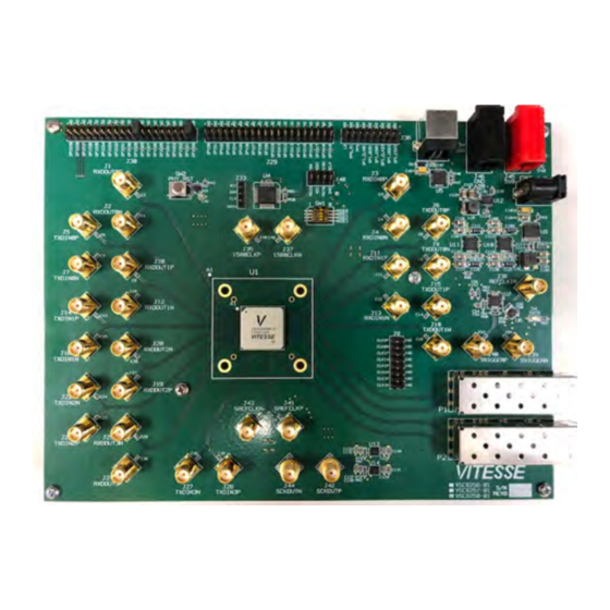
Page 4: Vsc8257/Vsc8258 Evaluation Board
Supporting 1000BASE-X, 10GBASE-R, 10GBASE-W, and other protocols, the VSC8258 is a quad serial Ethernet PHY with IEEE 1588-2008 and media access control security (MACsec) support. The VSC8257 is a quad serial Ethernet PHY with IEEE 1588-2008 support. MACsec functions are permanently disabled in a VSC8257 product. -
Page 5: Quick Start
VSC8257/VSC8258 Evaluation Board Quick Start The following items are recommended for use during evaluation of the evaluation board. VSC8257/8258 evaluation board (included in the kit) USB cable (included in the kit) GUI installation file (available on the website) SR/LR SFP+ module (not included) -
Page 6: Hardware Options
VSC8257/VSC8258 Evaluation Board Hardware Options The following sections describe the hardware options. Power Supply Options The evaluation board can also be powered by an external 5 V power supply. Use a pair of banana cables to connect a bench-style power supply capable of 4 A at 5 V to the board. Connect 5 V to J45 and GND to J46. -
Page 7: Software
VSC8257/VSC8258 Evaluation Board Software Although the device’s internal registers can be accessed through three different interfaces—MDIO, two- wire serial, or SPI—the software makes use of the SPI port. On the evaluation board, a F340 microcontroller acts as the SPI master that controls the PHY. The PC communicates with the microcontroller through a USB connection. -
Page 8: Main Page
VSC8257/VSC8258 Evaluation Board The GUI will detect the serial number of the connected evaluation board(s). If there are multiple boards connected on the same PC, click on the drop down menu, and select the desired evaluation board serial number. The two status lights will turn green when the F340 microcontroller is detected and the appropriate device is present. -
Page 9: Routing
VSC8257/VSC8258 Evaluation Board Figure 5 • GUI Main Page—PRBS31 Click Start Generator Start Checker to start the BIST. This begins the synchronization and error checking on the selected channel, along with a timer. The cumulative number of bit errors and the cumulative bit error rate are displayed. -
Page 10: Bist
VSC8257/VSC8258 Evaluation Board There are seven loopbacks available. Three of the loopbacks are host-side loopbacks. These include loopback H2, loopback H3, and loopback H4. Loopback H2 is the shallow loopback located in the XAUI- PHY block before the 8b/10b endec. The deeper loopback includes loopback H3 in the PCS block right after the 64b/66b gearbox and loopback H4 at the WIS block after the framer. -
Page 11: Sfp
VSC8257/VSC8258 Evaluation Board Table 1 • Generator Configuration (GEN_CFG), Address: 4xE900 Name Access Description Default 14:12 LENOFS Decrease pktlen by lenofs 11:4 SRATE Number of standard frames between PTP frames 0x00 IDLES Generate all idles 0: Generate frames 1: Generate idles only... -
Page 12: Rmon
VSC8257/VSC8258 Evaluation Board Figure 9 • GUI Register List Page The Register List page provides read and write access to device registers. They are grouped into nine tabs. To select a register, click on the name in the list. The register’s description, address, read/write capability, and current value are displayed. -
Page 13: I/O Control
VSC8257/VSC8258 Evaluation Board Figure 11 • GUI KR Status Page When the line side is connected to a link partner through a backplane, the KR mode could be enabled by clicking on config KR first and then KR enable . The user will see the green light move and it should eventually reside at AN_GOOD state and indicate KR (10G) is negotiated. -
Page 14: Command Line Interface
VSC8257/VSC8258 Evaluation Board Figure 13 • GUI Clocking Page In this page, there are actually two main categories: the source for the output clocks and the source for the lane sync feature. For the output clocks, CKOUTn, the user can first enable that output and then select if the output clock frequency should be divided by 1 or by 2. - Page 15 VSC8257/VSC8258 Evaluation Board The following images show the command line interface. Figure 14 • Command Line Interface I Figure 15 • Command Line Interface II ENT-AN1280 VPPD-04670 ENT-AN1280 User Guide Revision 1.3...
-
Page 16: Usage Examples
VSC8257/VSC8258 Evaluation Board Usage Examples The following sections describe usage examples. Packet BIST Go to the BIST page. Check the Enable box above Tx Packets sent to display the Tx packet sent. Then, check the Enable box under the BER to enable the packet BIST checker. The count of valid packets will be seen in the box for Good CRC and there are also counters for Bad CRC, Fragmentation, and Local Fault. - Page 17 Microsemi. It is the Buyer's responsibility to independently determine suitability of any products and to test and verify the same. The information provided by Microsemi hereunder is provided "as is, where is" and with all faults, and the entire risk associated with such information is entirely with the Buyer.
Need help?
Do you have a question about the VSC8257 and is the answer not in the manual?
Questions and answers