Table of Contents
Advertisement
Advertisement
Table of Contents

Related Manuals for Omron Enterprise Manager 2100


Summary of Contents for Omron Enterprise Manager 2100
- Page 1 Enterprise Manager 2100 User’s Guide I631-E-01...
- Page 2 The information contained herein is the property of Omron Adept Technologies, Inc., and shall not be reproduced in whole or in part without prior written approval of Omron Adept Tech- nologies, Inc. The information herein is subject to change without notice and should not be con- strued as a commitment by Omron Adept Technologies, Inc.
-
Page 3: Table Of Contents
Table of Contents Chapter 1: Introduction to the Enterprise Manager 2100 1.1 Description of the Enterprise Manager 2100 1.2 Number of AIVs Supported by an Enterprise Manager 2100 The Workspace Map Robot Jobs Communications Network 1.3 Hardware Supplied with the Enterprise Manager 2100... - Page 4 Ethernet Connections Configuration Tasks Overview 5.2 Set the IP Address on a Client PC's Network Adapter 5.3 Connect Your PC to SetNetGo on the Enterprise Manager 2100 Connect to SetNetGo and Configure Access and Security Enable Fleet Account Access Access SetNetGo from Mobile Planner 14413-200 Rev.
- Page 5 Manually Clearing (Flushing) the Entire Queue 6.4 Update the ARAMCentral Software Restarting ARAMCentral 6.5 Enterprise Manager 2100 Autosync Operation 6.6 Remove and Replace Enterprise Manager 2100 Appliances from Autosync Remove a Primary Appliance from Autosync Remove a Secondary Appliance from Autosync 14413-200 Rev. A...
- Page 6 Configure an EM1100 to EM2100 Configuration 6.9 Troubleshooting Including a debugInfo File with Your Help Request Chapter 7: Technical Specifications 7.1 Processing Specifications 7.2 Environmental Specifications 7.3 Power Requirements 7.4 Physical Characteristics 7.5 Connections Front Rear 14413-200 Rev. A Enterprise Manager 2100 User’s Guide...
-
Page 7: Chapter 1: Introduction To The Enterprise Manager 2100
1.7 How to Get Help 1.1 Description of the Enterprise Manager 2100 The Enterprise Manager 2100 is a hardware and software solution that enables you to manage a fleet of Automated Intelligent Vehicles (AIVs, also called robots in the software and doc- umentation). - Page 8 A typical installation is shown in Figure 1-1. The operator’s terminal, automated factory equip- ment, and WMS or MES systems all communicate directly with the Enterprise Manager 2100. Table 1-1. Description of the Main Components in an Enterprise Manager 2100 Installation...
-
Page 9: Number Of Aivs Supported By An Enterprise Manager 2100
1.2 Number of AIVs Supported by an Enterprise Manager 2100 The software license for a single Enterprise Manager 2100 supports an absolute limit of 100 AIVs. The actual number of AIVs that you can manage effectively is subject to practical oper- ational constraints. -
Page 10: Robot Jobs
Omron rep- resentative. Robot Jobs Your Enterprise Manager 2100 can support more AIVs if the job characteristics are as follows: AIV job routes are not complicated by many sub-tasks. Interaction with a Warehouse Management System (WMS) or Manufacturing Execution System (MES) is relatively simple and automated. -
Page 11: Optional Equipment
1.4 Features of the Enterprise Manager 2100 Key features of the Enterprise Manager 2100 and the Mobile Robot Software Suite, running on the Enterprise Manager appliance are: Provides the ability to manage the configuration settings for an entire fleet of AIVs. -
Page 12: Software Supplied With The Enterprise Manager 2100 Systems
The SetNetGo interface that is integrated into the licensed MobilePlanner software. Mobile Robot Software Suite Version 4.9.x The Mobile Robot Software Suite includes all of the software used for Omron Adept AIV's and the Enterprise Manager appliance, with the exception of the SetNetGo OS, which is supplied as a separate software package. -
Page 13: Mobileplanner In Fully Licensed Mode
ARAM manages wired and wireless Ethernet communications with offboard software, for external monitoring, development, and systems coordination, including coordination of a fleet of AIVs through the Enterprise Manager 2100 system. It also manages integration with other systems, as well as external monitoring, setup, and control with the MobilePlanner applic- ation. -
Page 14: Arcl Protocol
Call/Door Box Support—Call/Door Boxes are devices that you can use to summon an AIV remotely. These devices contain one software component on the boxes and while the other persists on either the Enterprise Manager 2100 or on single AIV, (when there is no Enterprise Manager 2100). -
Page 15: Enterprise Manager 2100 Autosync Failure Scenarios
EM2100 as the Primary. Configure the replacement EM2100 as a Secondary appliance and upload the SSL key from the Primary. 1.7 How to Get Help To obtain support assistance with your software or hardware, see the Omron Adept Tech- nologies, Inc. information on the website at: http://www.ia.omron.com. -
Page 16: Service And Support
1.7 How to Get Help Service and Support If, after reading this manual, you are having problems with your Enterprise Manager appli- ance, contact your local Omron support. Enterprise Manager 2100 User’s Guide 14413-200 Rev. A... -
Page 17: Chapter 2: Safety
2.2 Safety Precautions for the Enterprise Manager 2100 2.3 Disposal 2.1 Alert Levels There are three levels of alert notation used in Omron Adept Technologies, Inc. manuals. In descending order of importance, they are: DANGER: Identifies an imminently hazardous situation which, if not avoided, is likely to result in serious injury, and might result in fatality or severe property damage. -
Page 18: Alert Icons
NOTE: Information for more effective use of the product. Additional Information: Offers helpful tips, recommendations, and best prac- tices. Version Information: Information on differences in specifications for different versions of hardware or software. Enterprise Manager 2100 User’s Guide 14413-200 Rev. A... -
Page 19: Safety Precautions For The Enterprise Manager 2100
Chapter 2: Safety 2.2 Safety Precautions for the Enterprise Manager 2100 Read the installation and operation instructions before using the appliance. If you use the supplied rail kit to install the appliance into a 4-post datacenter rack, make sure you read and follow the safety instructions provided with the rack. -
Page 20: Additional Safety Information
Assurer la conformité avec tous les codes de sécurité et électriques locaux et nationaux lors de l'installation et du fonctionnement de l'équipement. Additional Safety Information Contact your local Omron support for other sources of safety information: 2.3 Disposal Dispose of in accordance with applicable regulations. -
Page 21: Chapter 3: Installation
For other technical specifications and requirements, see: Technical Specifications on page 79. Site Rack Requirements Each Enterprise Manager 2100 requires 1U (44.50 mm, 1.75 inches) of space in a standard 19- inch (48.3 cm) 4-post rack datacenter rack, installed as follows: The appliance requires a minimum of four support points at the sides, or a rack shelf that provides full support for the chassis enclosure. -
Page 22: Site Electrical Power Requirements
Complete any necessary electrical work in accordance with local regulations. Electrical installers must be suitably trained and qualified to perform the work. Omron Adept Technologies, Inc. recommends that you use an uninterruptible power supply (UPS) for the Primary appliance and a separate UPS for an optional Secondary appliance. If you do not use an UPS, and you install two appliances in the same rack, connect each appli- ance to different power distribution units (PDUs) on separate circuits for power redundancy. -
Page 23: Site Networking Requirements
Be aware of the specific requirements for wireless network coverage and bandwidth. Network resource availability can affect Enterprise Manager 2100 performance and the num- ber of AIVs supported. See also: Number of AIVs Supported by an Enterprise Manager 2100 on page 9. -
Page 24: Unpack The Shipment
Enterprise Manager 2100 on page 10. 3. Inspect each component for external damage as you unpack it. Contact your local Omron support immediately if you see any damage. See: How to Get Help on page 15. Unpack the Enterprise Manager 2100 Shipping Carton 1. -
Page 25: Sliding Rail Kit For Rack Mounting
5. Carefully lift out the appliance [1] and remove the four shock absorbing [2] corners and then remove the antistatic bag. 6. Put the packaging items back in the shipping carton and retain it for future use. Omron Adept recommends that you ship or move the appliance only in its original packaging. - Page 26 3.4 Sliding Rail Kit for Rack Mounting You cannot install the Enterprise Manager 2100 in a 2-post (Telco style) rack. The bezel brack- ets (ears) are not designed to support the chassis weight. However, you might be able to use 2-...
-
Page 27: Components In The Sliding Rail Kit
Components in the Sliding Rail Kit The sliding rail kit provided with your Enterprise Manager 2100 appliance includes: Inner sliding rail - Attach the rail to the appliance chassis. Adjustable telescoping track - Use adjustable brackets to attach the track to the rack posts. - Page 28 In addition, if you do not have the help of another person when mounting the track to the rack posts, a small spring clamp is useful to hold one end of the track in position as you work on the other end. Enterprise Manager 2100 User’s Guide 14413-200 Rev. A...
-
Page 29: Determine The Sliding Rail Kit Installation Location And Method
3. Repeat Step 1 and Step 2 for the second rail assembly. Attach the Sliding Rail to the Chassis Attach the sliding rail to the appliance chassis as follows: 14413-200 Rev. A Enterprise Manager 2100 User’s Guide... -
Page 30: Attach The Adjustable Brackets To The Track
3. Repeat Step 1 and Step 2 for the second sliding rail. Attach the Adjustable Brackets to the Track Attach the larger, adjustable L-shaped brackets to the telescoping track as follows: Figure 3-5. Attach the Large L-Brackets to the Track (Right Assembly Shown). Enterprise Manager 2100 User’s Guide 14413-200 Rev. A... -
Page 31: Determine The Mounting Method For The Sliding Rail Kit
Temporarily tape the rear L-bracket to the track to prevent it from moving. 4. Tighten the two 4mm M4 black screws and washers to secure the L-bracket to the track. Torque each screw to 2 ft-lb (3 N∙m). 14413-200 Rev. A Enterprise Manager 2100 User’s Guide... -
Page 32: Attach The Track To The Rack Posts
4. Repeat Step 2 for the L-clamp at the rear rack post [3]. 5. Repeat Step 1 through Step 4 for the remaining track. 6. Check that both slides operate smoothly and do not bind and that the tracks are level and straight. Enterprise Manager 2100 User’s Guide 14413-200 Rev. A... -
Page 33: Insert The Appliance Into The Track
5. Lock in place with an M5 screw. 3.5 Connect Power to the Enterprise Manager 2100 The appliance requires a 100 – 240 VAC, 50/60 Hz power supply. Omron Adept Technologies, Inc. recommends that you use a separate uninterruptable power supply (UPS) circuit for each appliance. -
Page 34: Plan For Disaster Tolerance
IMPORTANT: If you have an EM2100 and an EM1100, you must always use the EM1100 as a Secondary appliance. See Supported Enterprise Manager 2100 Deployments on page 14. If you install a Secondary appliance, follow the hardware procedure described for the Primary appliance. - Page 35 Chapter 3: Installation running you can quickly recover fleet operations. See Installing a Secondary Appliance on page 34. 14413-200 Rev. A Enterprise Manager 2100 User’s Guide...
-
Page 37: Chapter 4: Connectors And Indicators
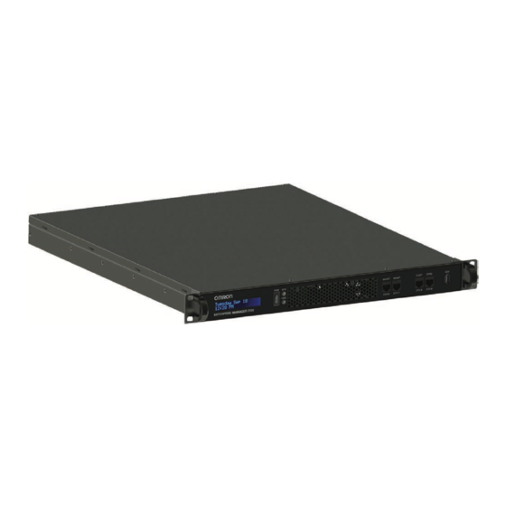
This section describes the connectors, indicators, and physical characteristics of the Enterprise Manager appliance, shown in Figure 4-1. Figure 4-1. Enterprise Manager 2100 Appliance Front Panel Features and Connectors The front panel features are described in Table 4-1. Table 4-1. EM2100 Front Panel features... -
Page 38: Rear Panel Connectors And Features
SVGA Video DB9 port, for service use only. Four auto-speed motherboard cooling fans. Fan speed (and noise volume) varies depending on the CPU load and the ambient temperature. Power supply cooling fan. Enterprise Manager 2100 User’s Guide 14413-200 Rev. A... -
Page 39: Enterprise Manager 2100 Status Display Panel
Mains power switch. Keep this set to on (I) and use the front power switch to control power. 4.3 Enterprise Manager 2100 Status Display Panel The Enterprise Manager 2100 includes an LCD status display panel that provides the inform- ation shown in Table 4-3. Table 4-3. Enterprise Manager 2100 Status Display Messages... -
Page 40: Connect The Enterprise Manager 2100 To A Network
4.4 Connect the Enterprise Manager 2100 to a Network 4.4 Connect the Enterprise Manager 2100 to a Network To use a single Enterprise Manager 2100 as a standalone appliance, connect the Ethernet ports as shown in Figure 4-3. Figure 4-3. Single Enterprise Manager 2100 as a Standalone Fleet Management Appliance Omron Adept Technologies, Inc. - Page 41 à un réseau LAN avec accès à Internet, assurer la présence d’un pare-feu entre le réseau LAN et Internet afin de prévenir le trafic réseau non désiré et non autorisé d’atteindre l’appareil Enterprise Manager.. 14413-200 Rev. A Enterprise Manager 2100 User’s Guide...
-
Page 42: Logical Ports And Protocols Used By The Enterprise Manager 2100
4.4 Connect the Enterprise Manager 2100 to a Network Logical Ports and Protocols Used by the Enterprise Manager 2100 An Enterprise Manager 2100 requires the logical ports and protocols described in Table 4-5. Table 4-5. Logical Ports and Protocols Protocol Port(s) Initiator to Recipient... -
Page 43: Logical Ports And Protocols Used By A Single Aiv
# Outgoing ARCL connection: If enabled in the configuration (Robot Interface and then Outgoing ARCL connection setup), then the AIV initiates an outgoing connection to the specified hostname and TCP port number. 14413-200 Rev. A Enterprise Manager 2100 User’s Guide... - Page 44 4.4 Connect the Enterprise Manager 2100 to a Network Protocol Port(s) Initiator ð Recipient Optional AIV to NTP server If the Network Time Protocol (NTP) client is enabled on the AIV (SetNetGo then System and then Date/Time), the AIV attempts to connect to the configured IP address to synchronize its clock.
-
Page 45: Chapter 5: Configuration
5.11 Customize Each Fleet AIV 5.12 Call Buttons 5.1 Enterprise Manager 2100 Configuration Overview Enterprise Manager 2100 Configuration varies depending on how you deploy the appliance. See Supported Enterprise Manager 2100 Deployments on page 14. Ethernet Connections The Enterprise Manager appliance provides four built-in Ethernet ports described in: Connect the Enterprise Manager 2100 to a Network on page 40. -
Page 46: Configuration Tasks Overview
Configure the network settings for the FLEET ETH2 Ethernet port. Define the login information. Configure each AIV to connect to the Enterprise Manager 2100. Customize each AIV, if desired. If you also install a Secondary appliance and configure Autosync, you must also: Install the same SetNetGo and ARAMCentral software version on the Secondary as is on the Primary appliance. -
Page 47: Set The Ip Address On A Client Pc's Network Adapter
SetNetGo on an AIV. The upper left of the screen shows SetNetGo - ENTERPRISE MANAGER 2100 or SETNETGO - LD, depending on your SetNetGo context (the device on which it runs, such as the Omron Adept Technologies, Inc. LD Plat- form). -
Page 48: Enable Fleet Account Access
5.3 Connect Your PC to SetNetGo on the Enterprise Manager 2100 Connect your browser to SetNetGo and configure SetNetGo access as follows: 1. Open a browser and type: HTTP://1. 2. 3. 4 and then press enter. 2. If a certificate warning dialog opens, ignore it and close the dialog. -
Page 49: Configure Management Interface Network Settings
A dedicated static IP address. (Do not use 1.2.3.4. That address is permanently assigned to the Maintenance Ethernet port.) The subnet mask for the Management network. The IP address of the network Gateway. 14413-200 Rev. A Enterprise Manager 2100 User’s Guide... -
Page 50: Configure The Fleet Interface Network Settings
A message dialog informs you of the status of the change, and whether there is any affect on operations such as a restart or a time delay before the change takes effect. Enterprise Manager 2100 User’s Guide 14413-200 Rev. A... -
Page 51: Use Ntp To Synchronize Enterprise Manager 2100 Time
Chapter 5: Configuration 5.6 Use NTP to Synchronize Enterprise Manager 2100 Time You can either specify the system time manually or configure the Enterprise Manager appli- ance to synchronize Network Time Protocol (NTP). When you use NTP: The Enterprise Manager appliance synchronizes its clock with NTP as a client of the NTP server. -
Page 52: Enabling The Arcl Server
The ARCL server enables automation systems such as WMS, MES or robot control application to communicate with the Enterprise Manager 2100 through a text -based TCP port. For more information about ARCL, see: Software Supplied with the Enterprise Manager 2100 Systems. -
Page 53: Fleet-Level Settings
Connection. Figure 5-4. Enterprise Manager Connection Screen 5. Check the ConnectToEnterpriseManager checkbox. 6. Enter the IP address of the Enterprise Manager 2100 appliance in the EnterpriseManagerAddress field. NOTE: This is the Fleet IP address, not the Management IP address of the Enterprise Manager appliance. -
Page 54: Add A Secondary Appliance For Autosync
45. 5.10 Configure a Secondary Appliance and Autosync The default (shipped) configuration for an Enterprise Manager 2100 is for Primary appliance operation. To create an Autosync pair, you use SetNetGo to configure the existing Primary to communicate with the Secondary. The paired appliances then function as follows: The Primary unit is a fully-functional Enterprise Manager appliance, running the Mobile Robot Software Suite and actively controlling the fleet. -
Page 55: Em2100-Only Autosync - Ethernet Cabling
Primary and Secondary FLEET ETH2 EM2100 and EM1100 Autosync — Ethernet Cabling Figure 5-6. shows the physical connection of cables to the appliances. Figure 5-6. Cabling for an EM2100 and EM1100 Autosync Configuration. 14413-200 Rev. A Enterprise Manager 2100 User’s Guide... -
Page 56: Tasks In Autosync Setup
5. You are prompted for a location to save the key file. Save the key locally on your PC, so you can later upload it to the Secondary appliance. 6. Enter a location (path) where you want to save the file. Enterprise Manager 2100 User’s Guide 14413-200 Rev. A... -
Page 57: Configure The Secondary Appliance
Not currently ignored by the AIV (because of previous failed attempts to dock). Docking Station Assignment There are three modes that you can use to specify an AIV's docking and battery charging beha- vior. To access the relevant docking parameters: 14413-200 Rev. A Enterprise Manager 2100 User’s Guide... -
Page 58: Default Mode
The Speech Synthesis section of parameters are now displayed on each AIV, and any voice that you set on an AIV is controlled by the AIV, rather than overwritten by the Mobile Robot Software Suite. Enterprise Manager 2100 User’s Guide 14413-200 Rev. A... -
Page 59: Call Buttons
If installed, you can use the call button option to request an AIV from a remote location. Pressing a call button sends a request to the Enterprise Manager 2100 system, requesting it to send an AIV to the call button's assigned goal. The Enterprise Manager 2100 responds by selecting an available AIV, and then assigning the call button's goal to that AIV. -
Page 61: Chapter 6: Operation
6.4 Update the ARAMCentral Software 6.5 Enterprise Manager 2100 Autosync Operation 6.6 Remove and Replace Enterprise Manager 2100 Appliances from Autosync 6.7 What to do if an EM2100 Primary Appliance Fails 6.8 What to do if an EM1100 Autosync Appliance Fails 6.9 Troubleshooting... -
Page 62: Hard Shutdown And Power Off
4. Follow the power-on steps described in: Safe Power On on page 61. Affect of Power Interruptions on an Enterprise Manager 2100 Omron Adept Technologies, Inc. recommends that you always use an uninterruptible power supply (UPS) to mitigate the affect of a power interruption. If you use two appliances in an Autosync configuration for operational redundancy, connect each appliance to separate power circuits and UPS devices. -
Page 63: Power Interruptions On An Autosync Enterprise Manager 2100
Restore power to the Secondary appliance. Fleet operations should be unaffected. If both Autosync appliances are affected by a power interruption, they both behave as described in: Power Interruptions on a Standalone Enterprise Manager 2100 on page 62: All fleet operations are terminated during the power interruption. -
Page 64: Generate A Workspace Map For Your Fleet
Pickup - a job segment that ends at a goal so that a payload is loaded onto the AIV. If the first segment of a job is a PICKUP, then the Enterprise Manager 2100 assigns this job to whichever AIV it decides is most appropriate. - Page 65 To complete the job the AIV requires no further job commands. The Enterprise Manager 2100 manages jobs associated with either a PICKUP or a DROPOFF goal. Any AIV tasks that are associated with the goals are executed at the proper times, though they are not managed as separate jobs in the queue.
-
Page 66: Queuing Examples
Interrupted - jobs that have been interrupted by an Operator manually controlling the AIV. These jobs are reassigned after a brief pause. Queuing Examples The following flowcharts represent sample usage scenarios, and require some application-layer support to fully implement. Enterprise Manager 2100 User’s Guide 14413-200 Rev. A... - Page 67 Operator inputs Operator may one or more add destinations destinations into AIV into AIV Operator refers to a human operator. Manager refers to queuing manager software. Figure 6-1. Manual Queuing Cycle 14413-200 Rev. A Enterprise Manager 2100 User’s Guide...
-
Page 68: Queuing Parameters
1. In MobilePlanner, open the Config tab. 2. Select Robot Operation and then Queuing Manager. The parameters that control the way that the Enterprise Manager 2100 handles queuing are: IdleTimeUntilResume - Number of minutes to wait, after an AIV becomes available, before automatically resuming an interrupted job. - Page 69 An AIV drives to a docking station any time that its state of charge falls below the limit set for AutoDockStateOfCharge even if it is performing a job. This is an AIV-level parameter, not visible or settable on the Enterprise Manager 2100. Omron Adept Technologies, Inc.recommends that at least a 10% difference between LowStateOfCharge and AutoDockStateOfCharge, to make sure that the AIV does not drive to a docking station while performing a job.
-
Page 70: Manually Clearing (Flushing) The Entire Queue
AIVs. Use ARAMCentral parameters only in limited circumstances, typically when working with your local Omron support. To clear the entire queue, temporarily add a special startup argument to ARAMCentral. The fol- lowing procedure clears the queue: 1. -
Page 71: Update The Aramcentral Software
2. Select Software and then Manage Installed Software. 3. Click Restart. 6.5 Enterprise Manager 2100 Autosync Operation Autosync provides operational redundancy if a problem occurs with the Primary appliance. During normal Autosync operation, you will observe changes only when either the Primary or Secondary appliance stops operating. -
Page 72: Remove And Replace Enterprise Manager 2100 Appliances From Autosync
To safely remove an Enterprise Manager 2100 Primary appliance from an Autosync con- figuration, you must promote the Secondary appliance to the Primary role as shown in 6.6 You can then safely remove the Primary as follows: 1. -
Page 73: Remove A Secondary Appliance From Autosync
IMPORTANT: This procedure assumes that you do not make any changes to the appliance configuration or to the software and data stored on the appliance. To remove an Enterprise Manager 2100 Secondary appliance from an Autosync configuration: 1. Verify that fleet operations are normal and job processing is on schedule. -
Page 74: What To Do If An Em2100 Primary Appliance Fails
Use the following procedure to replace a failed EM1100 Appliance with a replacement EM2100. 1. Power off the failed appliance and disconnect its power cable. 2. Remove the networking cables from the failed EM1100 appliance and physically remove it. Enterprise Manager 2100 User’s Guide 14413-200 Rev. A... - Page 75 The failed Primary has the queue file, which is no longer current. Before putting the failed Primary back into service, you should manually clear the queue. See Manually Clearing (Flushing) the Entire Queue on page 70. 14413-200 Rev. A Enterprise Manager 2100 User’s Guide...
-
Page 76: Troubleshooting
Verify ARAMCentral is running by checking logs in Network per- SetNetGo missions Verify firewall access error If using Autosync, verify autosync mode is set to Autosync Primary on only one Enterprise Manager configuration error Enterprise Manager 2100 User’s Guide 14413-200 Rev. A... -
Page 77: Including A Debuginfo File With Your Help Request
EM. For best results, install the same Mobile Software suite on all EMs and AIVs. If you are requesting help from Omron Adept Technologies, Inc., it is very useful to include a debugInfo file. Instructions for doing so follow. - Page 78 6.9 Troubleshooting 1. Select Status and then Debug Info. 2. Click Download debug info. 3. Save the file, and attach it to your support request. Enterprise Manager 2100 User’s Guide 14413-200 Rev. A...
-
Page 79: Chapter 7: Technical Specifications
Table 7-3. Power Specifications Input Voltage 100 - 240 VAC, 50/60 Hz Typical Power Consumption 100 W Maximum Power Consumption 200 W Appliance power inlet connector IEC 60320 C14 (Maximum 15 A, 250 V) 14413-200 Rev. A Enterprise Manager 2100 User’s Guide... -
Page 80: Physical Characteristics
Rail kit hole spacing 9.22 cm 3.63 inches Rail kit hole offset (from bracket) 10.44 cm 4.11 inches Max system width 48.26 cm 19.00 inches Securing hole spacing 45.55 cm 18.33 inches Enterprise Manager 2100 User’s Guide 14413-200 Rev. A... -
Page 81: Connections
30 x 25.625 x 7.75 (cm) (inches) 7.5 Connections Front 10/100/1000 Ethernet x 4 USB for service use Rear USB x 4 for service use VGA (HDB15F) for service use IEC AC Power inlet 14413-200 Rev. A Enterprise Manager 2100 User’s Guide... - Page 83 39, 57 Administrator 48 Advanced Robotics Automation Management 13 Advanced Robotics Command Language 14-15 AIV 8, 64 assigned job 64 configuration 54 connecting to appliance 52 customizing 57 jobs 10, 64 14413-200 Rev. A Enterprise Manager 2100 User’s Guide...
- Page 84 64 auto-synchronize 11 Automated Intelligent Vehicles 7 automation call button 59 system 14 autonomous 13 Autosync 14-15, 39 configure 54 operation 71 remove appliance 72 status 39, 57 boot errors 61 Enterprise Manager 2100 User’s Guide 14413-200 Rev. A...
- Page 85 50 management interface 50 network 49 secondary appliance 54 SetNetGo 47 connect to SetNetGo 47 connecting AIV 52 network 40 power 33 connections 45 network 40 connectors and indicators 37 14413-200 Rev. A Enterprise Manager 2100 User’s Guide...
- Page 86 10, 57 domain server 50 download map 64 dropoff 64 DSN 50 dynamic route adjustments 11 error information 37 log 77 Ethernet cabling 54 connections 40 port 39 status 39 Enterprise Manager 2100 User’s Guide 14413-200 Rev. A...
- Page 87 70 front power switch 39 gateway 49 generate a map 64 hard shutdown 62 hard stop 38 hazard 17 heartbeat 54 help 15, 77 How Can I Get Help? 15 14413-200 Rev. A Enterprise Manager 2100 User’s Guide...
- Page 88 64 dropoff 64 pickup 64 queue 64 required AIV 64 segment 64-65 states 66 LAN 8, 10 LCD 39 LED 38 power 61 license 10, 13 dongle 13 key 11 error 77 Enterprise Manager 2100 User’s Guide 14413-200 Rev. A...
- Page 89 64 workspace 64 MARC 13 firmware 14 MES 8, 11, 52 MGMT 56 mixed mode 58 mobile robots 11 Mobile Software suite 14 MobilePlanner 13-14, 45, 48 access 48 ARCL 52 14413-200 Rev. A Enterprise Manager 2100 User’s Guide...
- Page 90 NTP 51 Operation 61 operator 48 options 45, 54 overview configuration 45 em2100 37 password 47 ARCL 52 payload 10 PC client 11 pending job queue 54 peripherals 15, 59 permissions 48 Enterprise Manager 2100 User’s Guide 14413-200 Rev. A...
- Page 91 11, 14, 54 primary appliance failed 14-15 queue 64 flushing 70 id 65 managing 64 parameters 68 queuing 13 queuing manager 7, 11 rack-mount 10, 19 rail kit 19, 80 RAM 10 14413-200 Rev. A Enterprise Manager 2100 User’s Guide...
- Page 92 11, 14 configure 54 secondary appliance 54 failed 15 security 47 segment 65 separate dock 58 service 16, 38 SetNetGo 12, 45 access 47 connecting 47 security 47 settings fleet 53 network 49 Enterprise Manager 2100 User’s Guide 14413-200 Rev. A...
- Page 93 Autosync 39 Ethernet 39 jobs 66 panel 39 queue 66 status display panel 39 storage 10, 38 support 16, 77 support, contact information 15 SVGA 38 switch power 61 synchronize ethernet 38 14413-200 Rev. A Enterprise Manager 2100 User’s Guide...
- Page 94 71 UPS 11 USB 12, 38, 81 user 48 VGA 81 viewer 48 voice 58 warehouse management system 10 Web management interface 47 WEEE 20 WiFi 8 Windows client PC 12, 47 Enterprise Manager 2100 User’s Guide 14413-200 Rev. A...
- Page 95 13 bandwidth 10, 12 Ethernet 12 WMS 8, 10-11, 52 workspace 9, 13 map 54, 64 14413-200 Rev. A Enterprise Manager 2100 User’s Guide...
- Page 96 OMRON ADEPT TECHNOLOGIES, INC. No. 438A Alexandra Road # 05-05/08 (Lobby 2), 4550 Norris Canyon Road, Suite 150, San Ramon, CA 94583 U.S.A. © OMRON Corporation 2019 All Rights Reserved. Alexandra Technopark, Tel: (1) 925-245-3400/Fax: (1) 925-960-0590 In the interest of product improvement,...
Need help?
Do you have a question about the Enterprise Manager 2100 and is the answer not in the manual?
Questions and answers