Table of Contents
Advertisement
Quick Links
Advertisement
Table of Contents

Related Manuals for Xylem YSI ProDSS


Summary of Contents for Xylem YSI ProDSS
- Page 1 USER MANUAL DOCUMENT #626973-01REF ProDSS USER MANUAL...
- Page 2 This page left intentionally blank...
-
Page 3: Table Of Contents
Contents Introduction Safety Information Precautionary Symbols Product Components Battery Use and Battery Life Charging the Battery Pack Battery Replacement Connect the Handheld to the Cable Assembly ProDSS Sensor Installation/Removal Operation Keypad and Navigation Startup Navigation Main Display Description System Menu Sensor Menu Calibration Menu Files Menu... - Page 4 Maintenance and Storage ProDSS Handheld Instrument Cable, Bulkhead, and Connectors Sensor Guard Depth Sensor Maintenance and Storage Turbidity and Total Algae Sensors Conductivity/Temperature Sensor Dissolved Oxygen Sensor pH - pH/ORP Sensors ISE Sensors ProDSS Driver and KorDSS Software Installation Install the ProDSS Driver and KorDSS Software Accessories Ordering ProDSS Handhelds...
-
Page 5: Introduction
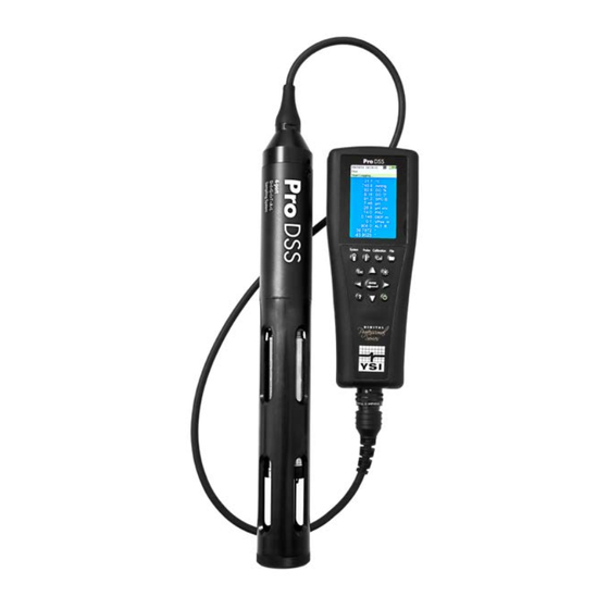
Introduction Thank you for purchasing the YSI Professional Digital Sampling System (ProDSS). ProDSS features include: • Digital smart probes that are automatically recognized by the instrument when connected • Waterproof (IP-67) case • Long-life rechargeable lithium-ion battery pack • Color display and backlit keypad •... -
Page 6: Battery Use And Battery Life
Introduction Battery Use and Battery Life The ProDSS uses a rechargeable lithium-ion (Li-Ion) battery pack as a power source. The battery comes pre-installed in the ProDSS and does not need to be replaced until the battery charge capacity is deemed unacceptable by the user. The battery is shipped at less than 50% full capacity and charging the battery is not required before first use. -
Page 7: Charging The Battery Pack
Introduction Charging the Battery Pack A USB cable is included with the ProDSS to charge the instrument battery pack and connect the instrument to a PC. The instrument battery pack can be charged from the AC power adapter, directly from a computer USB connection or from an external, portable USB battery pack (sold separately, see ProDSS accessories on Page 80). -
Page 8: Battery Replacement
Introduction Battery Replacement NOTE: The battery pack is pre-installed in the ProDSS instrument. WARNING: Do not charge or handle a battery pack that is hot to the touch. Failure to follow the safety warnings and precautions can result in personal injury and/or instrument damage not covered under warranty. - Page 9 Introduction Figure 2 Battery replacement 1 Battery pack cover 4 Instrument pin connectors 2 Battery pack 5 Battery pack gasket/cradle* 3 Battery pack connector 6 Battery pack gasket/cradle installed *Color shown for reference...
-
Page 10: Connect The Handheld To The Cable Assembly
Introduction Connect the Handheld to the Cable Assembly The ProDSS cable connectors are keyed for positive mating and to prevent connector damage (Figure 3). The ProDSS instrument retains its IP-67 rating when the cable is disconnected. However, the connectors are not wet-mateable and should be clean and dry before connecting. -
Page 11: Prodss Sensor Installation/Removal
Introduction ProDSS Sensor Installation/Removal ProDSS cable assemblies that feature user-replaceable sensors include 4 port cables with (626910 and 626911) and without (626909) a built-in depth sensor. This section pertains to these cable assemblies. Other ProDSS cable assemblies, like the ProDSS ODO/CT (627150), ProODO (626250) and ProOBOD (626400 and 626401), feature integral (i.e. - Page 12 Introduction 4. Carefully align the sensor and bulkhead connectors by inserting the sensor into the port then gently rotating the sensor until the connectors align. Once aligned, push the sensor toward the bulkhead until the sensor seats in the port. 5.
- Page 13 Introduction Sensor Guard and Weight Installation 1. Carefully slide the sensor guard over the bulkhead and attached sensors/port plugs. Push the sensor guard toward the bulkhead until the sensor guard threads align with the bulkhead threads. 2. Carefully finger-tighten the sensor guard clockwise. NOTICE: If any resistance is felt, loosen the sensor guard completely to prevent cross-threading.
- Page 14 Introduction Sensor Guard Weights To help stabilize the sensors when profiling at deeper depths, a 1 lb. sensor guard weight is supplied with 4 port assemblies 10 meters and longer. To attach the weight, carefully hand-tighten it clockwise on to the bottom of the sensor guard (Figure 6 on page 11).
-
Page 15: Operation
Operation Keypad and Navigation System Probe Calibration File ENTER Figure 7 Keypad description System: Opens the system menu. Use to adjust ON/OFF: Turn on or turn off the instrument system settings Exit/Escape key: Exits tot he Run screen. When in an Right arrow key: Navigate right in an alpha/ alpha/numeric entry screen, returns to previous menu numeric entry screen. -
Page 16: Startup
Operation Startup Push the key to turn on the handheld. If the handheld does not turn on, make sure that the battery pack is correctly installed and charged. Push and hold the key for 1.5 seconds to turn the handheld off. Navigation The ProDSS contains menus to change user-defined options, functions, and parameters. -
Page 17: Main Display Description
Operation Main Display Description The main display (Run screen) shows the current measurements as defined in the Sensor Display menu (“Sensor Display” on page 25). If more measurements are selected than can be displayed on the Run screen, a scroll bar will be shown. -
Page 18: System Menu
Operation System Menu ENTER Push the System key to view and adjust instrument settings. Highlight a sub-menu then push the key to view the sub-menu options (Figure 10). Pre-defined or user-selected options are noted within brackets ([]). See “Alpha/numeric entry” on page Use the System meu to: •... - Page 19 Operation Date/Time → Date/Time For accurate logging and GLP data, correctly set the date and time op- tions (Figure 11). Select any of the following options to set the Date/Time in the ProDSS. Date/Time options: • Set YY/MM/DD, MM/DD/YY, DD/MM/YY or YY/DD/MM date format Figure 11 Date/Time •...
- Page 20 Operation Re-Cal Prompts → → → Options Re-Cal Prompts Re-Cal Prompts provide a reminder to recalibrate a probe in the user-defined number of days (Figure 13). The Re-Cal prompt will be displayed in the message area of the main display when the set time has elapsed (Figure 9 on page 15).
- Page 21 Operation Date/Time → Language The ProDSS is shipped with English enabled. If a different language is desired and selected, the ProDSS will take approximately 10 to 20 seconds to enable the new language (during the first installation only). Otional languages: •...
- Page 22 Operation Continuous Mode ( Interval logging): Select the Continuous Mode check box and enter the user-defined Log Interval (in HH:MM:SS - hours:minutes:seconds) to log samples continuously at the specified time interval. The Run screen will display Start Logging... when in Continuous ENTER Mode.
- Page 23 Operation Radix Point → Radix Point The radix point can be changed to display a comma or a decimal in numeric displays (e.g. 1.00 becomes 1,000 when Comma is selected) Figure 20 Radix Point (Figure 20). Backlight → Backlight In Automatic mode, the instrument display will dim 60 seconds after the last key was pushed.
-
Page 24: Sensor Menu
Operation Unit ID → Unit ID Unit ID identifies the instrument in the KorDSS PC software program that was included with the instrument. Select Unit ID to change the default ID. Sensor Info → Sensor Info Sensor info shows measurement data, and hardware/software information for each component of the system: instrument, sensor, and bulkhead. - Page 25 Operation Sensor Setup → Setup The Sensor Setup menu will show all sensors connected to the instrument (Figure 23). If a sensor is connected but is not listed on the Sensor Setup menu (<None> displayed), check the sensor and cable connections (“ProDSS sensor installation/removal”...
- Page 26 Operation Setup pH → → Setup Select USA auto-buffer recognition (4.00, 7.00, and 10.00) or NIST auto- buffer recognition (4.01, 6.86, and 9.18) (Figure 26). Calibration values are Figure 26 Setup pH automatically compensated for temperature for both buffer sets. Setup Conductivity →...
- Page 27 Operation Setup Depth → → Setup Depth For ProDSS bulkheads with the depth sensor: Figure 28 Setup Depth The ProDSS cable assemblies with a depth sensor in the bulkhead can measure virtual vented depth. The virtual vented depth measurement allows for real time compensation for atmospheric pressure using the instrument’s barometer.
- Page 28 Operation Auto Stable → Auto Stable Auto Stable indicates when a measurement is stable. Sensors with Auto Stable enabled will have flash beside the measurement on the Run screen. will flash green when the measurement is stable. Select a sensor to enable or disable Auto Stable. Set the stability threshold parameters (Figure 30).
- Page 29 Operation Averaging → Averaging (Figure The averaging mode determines how the ProDSS will filter data. A smaller time frame for the rolling average window allows changes in the sensor’s measurements to be more quickly observed, while a larger rolling window provides more stable measurement readings and a smooth result.
-
Page 30: Calibration Menu
Operation GPS (Optional) → GPS turns the ProDSS Global Positioning System On or Off. The symbol is shown when a GPS signal is received (Figure 33). Figure 33 GPS When enabled, the GPS coordinates will be saved with the GLP file and logged data. -
Page 31: Files Menu
Operation Files Menu ENTER Push the key to access the Files menu (Figure 35). Highlight a sub-menu then push the key to view sub- menu options. Use the Files menu to view, delete or backup logged data or the GLP file. Data can be filtered by a specific date and time range and by user-created site and Data ID lists. - Page 32 Operation View Data Filter → View GLP Select View GLP to show the stored sensor calibrations (Figure 38). Use the arrow keys to scroll through the GLP file data. GLP Saved Information Information in each GLP record • Sensor calibrated •...
- Page 33 Operation Backup Data → Backup Data This function allows you to backup logged data to a flash drive based on Site, Data ID, and log date (Figure 40). A USB female to micro USB male adapter is included with new instruments for this data backup. NOTE: The USB storage device must be formatted as FAT32, not NTFS or exFAT.
-
Page 34: Taking Measurements
Operation Taking Measurements For the highest accuracy, calibrate the instrument before taking measurements (“Calibration” on page 33). 1. Create site and Data ID lists for logged data (if applicable) (“Logging” on page 19). 2. Set the logging method (single or interval) (“Logging”... -
Page 35: Calibration
Calibration ProDSS sensors (except temperature) require periodic calibration to maintain accurate measurements. Calibration procedures follow the same basic steps with variations for specific parameters. Before Calibration • Enter GLP user-defined data if applicable to user requirements (User ID, Probe ID, User Field #1/2) (GLP Options on page 17). - Page 36 Calibration Calibration Cup Installation 1. Ensure the calibration cup gasket is correctly seated (Figure 43). Loosely install the retaining nut on the cup. 2. Slide the calibration cup over the sensors and sensor guard and tighten the retaining nut. 1 Fill line one (used for Turbidity, pH, ORP, PC, PE, and chlorophyll calibration solutions) 2 Fill line two (used for conductivity...
-
Page 37: Conductivity
Calibration Conductivity A conductivity/temperature sensor must be installed on the bulkhead (Figure 4 on page 9) for accurate temperature compensation and measurements of all parameters except turbidity and TSS. Temperature calibration is not available or required for accurate temperature measurements. The conductivity/temperature sensor can measure and calculate conductivity, specific conductance (temperature compensated conductivity), salinity, non-linear function (nLF) conductivity, TDS, resistivity, and density. -
Page 38: Barometer
Calibration NOTE: If the data is not stabilized after 40 seconds, gently rotate the sensor or remove/reinstall the calibration cup to make sure that no air bubbles are in the conductivity cell. NOTE: If the actual measurement data is about 1/2 if the expected calibration value, the conductivity sensor is not completely submerged. -
Page 39: Dissolved Oxygen
Calibration Dissolved Oxygen ODO calibration requires the current “true” barometric pressure. Make sure that the barometer is reading accurately and recalibrate the barometer as necessary. ODO% and ODO% Local - Water Saturated Air Calibration NOTE: This method calibrates the instrument’s DO% measurement or DO% Local measurement if DO% local is enabled in the sensor setup menu. - Page 40 Calibration ODO mg/L Calibration 1. Place the ODO and conductivity/temperature sensor into a water sample that has been titrated by the Winkler method to determine the dissolved oxygen concentration in mg/L. 2. Push the key, then select ODO. Select DO mg/L. 3.
-
Page 41: Ph/Orp
Calibration pH/ORP pH Calibration 1-Point NOTE: If performing a 1-point calibration, use buffer 7 (6.86) as your calibration point for highest accuracy. NOTE: Observe the pH mV readings during calibration to understand the condition and response of the pH sensor. In buffer 7, pH mVs should be between -50 and +50. - Page 42 Calibration pH Calibration 2- or 3-Point NOTE: If performing a 2- or 3-point calibration, one point should be in buffer 7; however, the calibration points can be in any order. 1. Perform steps 1-7 of the pH calibration 1-point procedure (“pH calibration 1-point”...
-
Page 43: Depth
Calibration Depth NOTE: This calibration option is available only if your bulkhead is equipped with a depth sensor. The depth sensor is located where the cable connects to the bulkhead (Figure 63 on page 60). For the calibration, make sure that the depth sensor is clean and in air, not immersed in any solution. For highest accuracy, keep the bulkhead still and in one position while calibrating. -
Page 44: Turbidity
Calibration Turbidity Before performing the calibration, review “Calibration setup (pH, ORP, ISE, conductivity, turbidity, and total algae sensors)” on page For proper calibration, you must use standards that have been prepared according to details in Standard Methods for the Treatment of Water and Wastewater (Section 2130 B). Acceptable standards include: •... - Page 45 Calibration Turbidity Calibration 1-, 2- or 3-Point NOTE: The sensor guard must be installed for the turbidity sensor calibration. NOTE: When performing a turbidity calibration, the first point must be zero.Select Calibration Value and enter 0.00. 1. Perform the “Calibration setup (pH, ORP, ISE, conductivity, turbidity, and total algae sensors)”...
-
Page 46: Total Algae
Calibration Total Algae The Total Algae (TAL) sensors are dual-channel fluorescence sensors. The channels on the TAL-PC sensor refer to two independent data sets: one results from a blue excitation beam that excites the chlorophyll a (chl) molecule and the second results from an orange excitation beam that excites the phycocyanin (PC) accessory pigment. The TAL-PE sensor is similar, also having the chlorophyll channel, but rather than an orange excitation beam there is a slightly blue- shifted beam that excites phycoerythrin (PE), rather than PC. - Page 47 Calibration Number of Calibration Points A 1- or 2-point calibration can be completed for all channels on the TAL-PC and TAL-PE sensors. A 1-point calibration, typically completed in clear deionized or distilled water, is simply a re-zeroing of the sensor. Although a 1-point calibration is more convenient (faster and no Rhodamine WT solution is needed), a 1-point calibration does not reset the second point entered during the most recent 2-point calibration.
- Page 48 Calibration Rhodamine WT Dye Solution Preparation Rhodamine WT dye solution must be used when completing a 2-point calibration. Purchase Rhodamine WT as a 2.5% solution to follow the procedure below. Note that there are many types of Rhodamine—make sure Rhodamine WT is selected.
- Page 49 Calibration Chlorophyll Phycocyanin Phycoerythrin Temp (°C) 14.0 56.5 11.4 11.4 37.3 104.0 14.6 58.7 13.1 13.1 39.1 109.0 15.2 61.3 14.1 14.1 41.0 115.0 15.8 63.5 15.0 15.0 43.0 120.0 16.4 16.0 16.0 45.0 126.0 17.0 68.4 17.1 17.1 47.0 132.0 17.6 70.8...
- Page 50 Calibration PE, PC and Chlorophyll Calibration 1- or 2-Point NOTE: The sensor guard must be installed and the calibration cup must be used during calibration. NOTE: Each channel of the sensor must be calibrated independently. Calibration of the chlorophyll channel does not set the calibration for the PC channel or the PE channel.
- Page 51 Calibration 8. Rinse the sensors, calibration cup, and sensor guard 2-3 times with a small amount of standard #2. Discard the standard after each rinse. Blot the sensor dry with a lint-free cloth. NOTE: For standard #2, use the 0.625 mg/L Rhodamine WT solution when calibrating chlorophyll (RFU or µg/L) on either TAL sensor, or when completing a PC (RFU or µg/L) calibration on a TAL-PC sensor.
-
Page 52: Ises: Ammonium, Nitrate, & Chloride
Calibration ISEs: Ammonium, Nitrate, & Chloride Before performing the calibration, review “Calibration setup (pH, ORP, ISE, conductivity, turbidity, and total algae sensors)” on page The ISE sensors can be calibrated to one, two or three points. A 2-point calibration without chilling a third calibration solution is extremely accurate and is the preferred method. - Page 53 Calibration ISE Calibration 3-Point 1. Perform the “Calibration setup (pH, ORP, ISE, conductivity, turbidity, and total algae sensors)” on page 33. Rinse the sensor 2-3 times with a small amount of standard #1. NOTE: It is best to calibrate in order of increasing concentration (e.g.
- Page 54 Calibration Chilled Third Calibration Point The 3-point calibration method assures maximum accuracy when the temperature of the media to be monitored cannot be anticipated. If you must perform a chilled 3-point calibration, the following procedure requires one portion of the high concentration calibration solution and two portions of the low concentration calibration solution. The high concentration solution and one of the low concentration solutions should be at ambient temperature.
- Page 55 Calibration Preparing Chloride Standards The following recipes are provided for preparation of 10 and 1000 mg/L chloride reagents. Nitrate and Ammonium standards can be purchased from YSI or other laboratory supply companies. WARNING: Some of the chemicals required for these solutions could be hazardous under some conditions. It is the responsibility of the user to obtain and study the MSDS for each chemical and to follow the required instructions with regard to handling and disposal of these chemicals.
- Page 56 Calibration Preparing Nitrate Standards We recommend using YSI calibration solutions whenever possible. However, qualified users can save cost by following these recipes for 1 and 100 mg/L nitrate standards. Other concentrations can be made by altering the amount of potassium nitrate. All other concentrations should remain unchanged. CAUTION: Some of these chemicals are hazardous and therefore, the standards should only be prepared by qualified chemists in laboratories where proper safety precautions are possible.
- Page 57 Calibration Preparing Ammonium Standards We recommend using YSI calibration solutions whenever possible. However, qualified users can save cost by following these recipes for 1 and 100 mg/L standards. Other concentrations can be made by altering the amount of ammonium chloride. All other ingredient concentrations should remain unchanged. CAUTION: Some of these chemicals are hazardous and therefore, the standards should only be prepared by qualified chemists in laboratories where proper safety precautions are possible.
- Page 58 Calibration This page left intentionally blank...
-
Page 59: Maintenance And Storage
Maintenance and Storage Follow all maintenance and storage procedures in this section. NOTICE: Incorrect or unapproved maintenance and/or storage can cause handheld, sensor or cable damage not covered by the warranty. Unless otherwise specified, storage terms are defined as follows: Short-term storage (less than 4 weeks): Storage when the ProDSS will be used at regular intervals (daily, weekly, biweekly, etc.) Long-term storage: Storage when the ProDSS will have long periods of inactivity (over winter, end of monitoring... -
Page 60: Prodss Handheld Instrument
Maintenance and Storage ProDSS Handheld Instrument Handheld Instrument Maintenance Wipe the keypad, screen, and case with a cloth dampened with a mild solution of clean water and dish soap (Figure 60). Handheld Storage Temperature Optimal storage temperature of the handheld instrument: •... -
Page 61: Cable, Bulkhead, And Connectors
Maintenance and Storage Cable, Bulkhead, and Connectors Cable, Bulkhead, and Connector Maintenance Wipe the bulkhead cable with a cloth dampened with a mild solution of clean water and dish soap. NOTICE: Install sensors or port plugs in ProDSS 4 port cable assemblies so the bulkhead ports do not get wet when cleaning. -
Page 62: Depth Sensor Maintenance And Storage
Maintenance and Storage Depth Sensor Maintenance and Storage Depth Sensor Storage The ProDSS optional depth sensor on 4 port ProDSS cables accesses water through ports located in the bulkhead (Figure 63). Although not directly accessible, correct maintenance and storage is necessary for reliable operation. -
Page 63: Turbidity And Total Algae Sensors
Maintenance and Storage Turbidity and Total Algae Sensors Turbidity and Total Algae Sensor Maintenance Clean the sensing window with a non-abrasive, lint-free cloth (Figure 64). NOTICE: Clean the window carefully to prevent scratches. If necessary, use mild soapy water. Figure 64 Sensor window Turbidity and Total Algae Sensor Short-Term Storage (Less Than 4 Weeks) When in regular field use, the turbidity and total algae sensors can remain... -
Page 64: Conductivity/Temperature Sensor
Maintenance and Storage Conductivity/Temperature Sensor NOTICE: Use care when handling the conductivity/temperature sensor to prevent any impact on the exposed thermistor. Conductivity/Temperature Sensor Maintenance 1. Dip the sensor’s cleaning brush (included with the maintenance kit) in clean water. 2. Insert the brush at the top of the channels, and sweep the channels 15 to 20 times (Figure 66). -
Page 65: Dissolved Oxygen Sensor
Maintenance and Storage Conductivity/Temperature Sensor Long-Term Storage The Conductivity/Temperature sensor can be stored dry or wet. For ProDSS 4 port cable assemblies, the sensor can be installed on the bulkhead or detached (Figure 68). Figure 68 Conductivity/Temperature long-term storage Dissolved Oxygen Sensor ODO sensor caps are warranted for 1 year but have a typical working life of 18 to 24 months. - Page 66 Maintenance and Storage Sensor Cap Replacement - ProDSS ODO Sensors 1. Turn the used sensor cap counterclockwise to remove it from the sensor. NOTE: If possible, do not use a tool to remove the cap from the sensor. If necessary, carefully turn the cap counterclockwise with pliers until it breaks loose.
- Page 67 Maintenance and Storage Updating the ODO Sensor Cap Coefficients After installing a new sensor cap, connect the bulkhead cable assembly to the ProDSS instrument and turn the instrument on. Locate the Calibration Code Label on the ODO sensor cap instruction sheet and note the eight sequences of letters and/or numbers listed as K1 through K7 and KC.
- Page 68 Maintenance and Storage ODO Sensor Rehydration To prevent sensor drift, always store the ODO sensor in a wet or water-saturated air environment. If the ODO sensor has accidentally been left dry for longer than 8 hours, it must be rehydrated. If rehydration is necessary, soak the ODO sensor cap in warm (room temperature) tap water for approximately 24 hours.
-
Page 69: Ph - Ph/Orp Sensors
Maintenance and Storage pH - pH/ORP Sensors NOTE: pH and pH/ORP sensors require periodic maintenance to clear contamination from the sensing elements. These contaminants can slow sensor response time. Clean the sensors when deposits, bio-fouling or other contamination appears on the glass or when the sensor response time is noticeably slow. NOTICE: Do not physically scrub or swab the glass bulb. - Page 70 Maintenance and Storage pH - pH/ORP Sensor Storage The pH - pH/ORP sensors are shipped with their tips in a storage bottle containing KCl. Store the pH - pH/ORP sensors in the shipping container when not in use. pH - pH/ORP Sensor Short-Term Storage (Regular Use, Daily, Weekly, Biweekly) When in regular field use, the pH-pH/ORP sensors should remain on the bulkhead with the storage cup installed.
-
Page 71: Ise Sensors
Maintenance and Storage ISE Sensors Do not let the ISE sensor reference electrode junctions dry out. Clean the sensors when deposits, bio-fouling or other contamination appears on the membrane. Ammonium and Nitrate Sensor Maintenance 1. Carefully clean the ammonium or nitrate sensor by rinsing with DI water followed by soaking in the high standard calibration solution (Figure 77). - Page 72 Maintenance and Storage ISE Sensor Short-Term Storage (Less Than 4 Weeks) When in regular field use, the ISE sensors should remain installed on the bulkhead in an environment of water-saturated air. Place approximately 0.5 in (1 cm) of any water (deionized, distilled or environmental) in the calibration cup (Figure 79).
- Page 73 Maintenance and Storage ProDSS sensor module replacement ProDSS pH, pH/ORP, ammonium, chloride and nitrate sensors feature replaceable sensor modules. These modules can be replaced by the user as needed. Typical working life of a pH or pH/ORP sensor module is 18 to 24 months. Typical working life of ammonium, chloride and nitrate sensor modules is 4 to 8 months.
- Page 74 Maintenance and Storage This page left intentionally blank...
-
Page 75: Prodss Driver And Kordss Software Installation
ProDSS Driver and KorDSS Software Installation NOTE: YSI recommends that you have administrative privileges on the PC in which the ProDSS driver and KorDSS will be installed. This level of permission will allow the user to install software onto the PC. A warning will commonly indicate that software installation cannot be completed due to the lack of administrative privileges. -
Page 76: Install The Prodss Driver And Kordss Software
KorDSS Software Installation Install the ProDSS Driver and KorDSS Software NOTE: It is recommended to install the ProDSS driver before connecting the ProDSS to your PC. 1. Insert the supplied USB flash drive into a USB port on your computer. 2. -
Page 77: Accessories
Accessories Ordering Telephone: 800 897 4151 (USA) +1 937 767 7241 (Globally) Monday through Friday, 8:00 AM to 5:00 ET Fax: +1 937 767 9353 (orders) Email: info@ysi.com Mail: YSI Incorporated 1725 Brannum Lane Yellow Springs, OH 45387 USA Internet: ysi.com When placing an order please have the following available: 1. -
Page 78: Prodss Handhelds
Accessories ProDSS Handhelds YSI Item # Description 626870-1 ProDSS handheld, no GPS 626870-2 ProDSS handheld with GPS ProDSS 4 Port Cable Assemblies (No Sensors Included) YSI Item # Description 626909-1 ProDSS-1 meter 4 port cable assembly, no depth 626909-4 ProDSS-4 meter 4 port cable assembly, no depth 626909-10 ProDSS-10 meter 4 port cable assembly, no depth 626909-20... -
Page 79: Replacement Sensor Modules And Odo Sensor Caps
Accessories Replacement Sensor Modules and ODO Sensor Caps YSI Item # Description 626890 Replacement ProDSS Optical Dissolved Oxygen sensor cap (for 626900 smart sensor) 626320 Replacement ProODO Optical Dissolved Oxygen sensor cap (for 626250 probe/cable assemblies) 626482 Replacement ProOBOD Optical Dissolved Oxygen sensor cap (for 626400 or 626401 lab probes) 627160 Replacement ProDSS ODO/CT ODO Sensor Cap (for 627150 probe/cable assemblies) - Page 80 Accessories ProODO/ProOBOD sensor and cable assemblies - DO/Temp only NOTE: ProODO/ProOBOD cable assemblies feature non-replaceable temperature and optical DO sensors. Sensor caps for optical DO sensors are replaceable (626320 for ProODO cable assemblies; 626482 for ProOBOD cable assemblies). There is no depth option with ProODO/ProOBOD cable assemblies. YSI Item # Description 626250-1...
-
Page 81: Calibration Standards
Accessories Calibration standards YSI Item # Description 065270 Conductivity standard, 1000 mhos/cm (quart, glass); ideal for fresh water 065272 Conductivity standard, 10000 mhos/cm (quart, glass); ideal for brackish water 065274 Conductivity standard, 100000 mhos/cm (quart, glass); ideal for supersaturated sea water 060907 Conductivity standard, 1000 mhos/cm (box of 8 individual pints, plastic);... -
Page 82: Prodss Accessories
Accessories ProDSS Accessories YSI Item # Description 626946 Large, hard-sided carrying case (Fits ProDSS 4 port cables 10, 20, and 30 meters in length, cable management kit, handheld, and accessories) 603075 Large, soft-sided carrying case 626945 Small, hard-sided carrying case (Fits ProDSS 4 port cables 1 and 4 meters in length, handheld, flow cell, and accessories) 599080 Flow cell for ProDSS 4 port cables... -
Page 83: Safety And Support
Safety and Support Rechargeable Lithium-Ion Battery Pack Safety Warnings and Precautions CAUTION: Failure to follow the safety warnings and precautions can result in fire, personal injury and/or equipment damage not covered under warranty. CAUTION: If the internal battery fluid comes into contact with skin, wash the affected area(s) with soap and water immediately. - Page 84 Safety and Support Charging/Discharging/Handling the Battery Pack WARNING: Failure to follow the battery pack charging/discharging instructions can cause the battery to become hot, rupture or ignite and cause serious injury and/or equipment damage. WARNING: Only charge the battery using charging devices designed specifically for the ProDSS by YSI. Use of unapproved chargers can result in battery failure and potentially serious injury to the user.
-
Page 85: Service Information
Safety and Support Service Information YSI has authorized service centers throughout the United States and Internationally. For the nearest service center information, please visit ysi.com and click ‘Support’ or contact YSI Technical Support directly at 800-897-4151 (+1 937-767-7241). When returning a product for service, include the Product Return form with cleaning certification. The form must be completely filled out for a YSI Service Center to accept the instrument for service. -
Page 86: Declaration Of Conformity
4. Immunity to Surge, IEC 61000-4-5:2005 5. Radio Frequency, Continuous Conducted Immunity, IEC61000-4-6:2008 6. IEC 61000-4-8:2009 7. IEC 61000-4-11:2004 Authorized EU Xylem Analytics UK Ltd Representative Unit 2 Focal Point, Lacerta Court, Works Road Letchworth, Hertfordshire, SG6 1FJ UK Signed: Lisa M. Abel... - Page 87 Safety and Support The undersigned hereby declares on behalf of the named manufacturer under our sole responsibility that the listed product conforms to the requirements for electrical equipment under US FCC Part 15 and ICES-003 for unintentional radiators. Manufacturer: YSI Incorporated 1725 Brannum Lane Yellow Springs, OH 45387 Product Name:...
-
Page 88: Warranty
Safety and Support Warranty The YSI Professional Digital Sampling System (ProDSS) is warranted for three (3) years from date of purchase by the end user against defects in materials and workmanship. The ProDSS bulkhead, sensors and cable (ProDSS 4 port, ProDSS ODO/CT, ProODO, and ProOBOD) assemblies are warranted for two (2) years from date of purchase by the end user against defects in material and workmanship. -
Page 89: Appendix A - Do% Calibration Values
Safety and Support Appendix A - DO% Calibration Values Calibration Value Pressure D.O. % in Hg mmHg mbar 101% 30.22 767.6 102.34 1023.38 100% 29.92 760.0 101.33 1013.25 29.62 752.4 100.31 1003.12 29.32 744.8 99.30 992.99 29.02 737.2 98.29 982.85 28.72 729.6 97.27... - Page 90 Appendix A - DO% Calibration Values This page left intentionally blank...
-
Page 91: Appendix B - Oxygen Solubility Table
Title Appendix B - Oxygen Solubility Table Solubility of oxygen in mg/L in water exposed to water-xaturated air at 760 mm Hg pressure. Salinity = Measure of quantity of dissolved salts in water. Chlorinity = Measure of chloride content, by mass, of water. S(0/00) = 1.80655 x Chlorinity (0/00) Temp °C Chlorinity : 0... - Page 92 Appendix B - Oxygen Solubility Table Temp °C Chlorinity : 0 5.0 ppt 10.0 ppt 15.0 ppt 20.0 ppt 25.0 ppt Salinity: 0 9.0 ppt 18.1 ppt 27.1 ppt 36.1 ppt 45.2 ppt 33.0 7.18 6.84 6.52 6.21 5.91 5.63 34.0 7.07 6.73...
Need help?
Do you have a question about the YSI ProDSS and is the answer not in the manual?
Questions and answers