
Related Manuals for Arista 7300 Series


Summary of Contents for Arista 7300 Series
- Page 1 Quick Start Guide 7300 Series Modular Data Center Switches DCS-7304 DCS-7308 DCS-7316 Arista Networks www.aristanetworks.com PDOC-00040-02...
- Page 2 © Copyright 2014 Arista Networks, Inc. The information contained herein is subject to change without notice. Arista Networks and the Arista logo are trademarks of Arista Networks, Inc in the United States and other countries. Other product or service names...
-
Page 3: Chapter 1 Overview
Important! Ultimate disposal of this product must be handled in accordance with all national laws and regulations. Safety Information Refer to the Arista Networks document Safety Information and Translated Safety Warnings available at: http://www.aristanetworks.com/en/support/docs/eos 7300 Series Modular Switch Quick Start Guide... -
Page 4: Obtaining Technical Assistance
Chapter 1: Overview Obtaining Technical Assistance Any customer, partner, reseller or distributor holding a valid Arista Service Contract can obtain technical support in any of the following ways: • Email: support@aristanetworks.com. This is the easiest way to create a new service request. -
Page 5: Chapter 2 Preparation
Load the switch at the bottom if it is the only item in the rack. The accessory kit provides mounting brackets for four-post racks. Contact your sales representative to obtain two-post mounting racks. 7300 Series Modular Switch Quick Start Guide PDOC-00040-02... -
Page 6: Tools Required For Installation
Minimize handling of assemblies and components. • Keep replacement parts in their original static-free packaging. • Remove all plastic, foam, vinyl, paper, and other static-generating materials from the work area. • Use tools that do not create ESD. Arista Networks Copyright 2014... -
Page 7: Chapter 3 Rack Mounting The Switch
Step 2 Attach both center-mount brackets to the chassis with the provided M4x8 panhead Phillips screws. Secure the bracket by attaching screws through each bracket hole. Figure 2: Attaching the Center-mount Brackets 7300 Series Modular Switch Quick Start Guide PDOC-00040-02... -
Page 8: Inserting The Switch Into The Rack
Step 3 Select mounting screws that fit your equipment rack. Step 4 Attach the bracket flanges to the rack posts. Secure the switch to the rack with screws through each bracket hole. After completing the two-post installation, proceed to Chapter Arista Networks Copyright 2014... -
Page 9: Four-Post Rack Mount
(Insets A and B). To install shelves into posts with threaded or rounded holes, remove all plugs from the shelves, then attach the shelves with bolts that fit the rack. Figure 5: Right Shelf – Outer View 7300 Series Modular Switch Quick Start Guide PDOC-00040-02... -
Page 10: Mounting Ears
(first RU and first hole), the mounting ears are placed as follows: • 7304: 8th RU (22nd through 24th holes) • 7308: 13th RU (37th through 39th holes) • 7316: 21st RU (61st through 63rd holes) Figure 7: Component Placement Arista Networks Copyright 2014... -
Page 11: Switch Mounting Process
Figure 8: Attaching the Right Shelf Step 3 Close the front locking mechanism latch (Figure Step 4 Glide the slide-end to a position outside of its rear rack post (Figure Figure 9: Adjusting the Right Shelf 7300 Series Modular Switch Quick Start Guide PDOC-00040-02... -
Page 12: Mounting Ear Installation
Step 1 Install the mounting ear on the front post by inserting the front rack plugs and guide pins in the racks specified for the switch model that is being installed (Figure 11). Figure 11: Attaching the Right Mounting Ear Step 2 Close the front locking mechanism latch (Figure Arista Networks Copyright 2014... - Page 13 Step 3 Lift the chassis into the rack. Step 4 Secure the chassis by tightening the six thumbscrews on the front flanges into the rack posts. After completing the Four-Post Installation, proceed to Chapter 7300 Series Modular Switch Quick Start Guide PDOC-00040-02...
-
Page 14: Chapter 4 Cabling The Modular Switch
(Figure 14) or the rear panel (Figure 15 depicts the location on the 7304). Receptacles are available in similar locations on other switch models. Figure 15: ESD Grounding Port – Rear Panel Arista Networks Copyright 2014... -
Page 15: Connecting Power Cables
Table 2 lists the quantity of modules each chassis can contain and the minimum operating requirements for each model. Table 2: Power Supply Capacity and Requirements for 7300 Series Modular Switches Switch Model Chassis Capacity Minimum Operaitng Requirements... -
Page 16: Connecting Supervisor Cables
Supervisor modules contain console, management, and USB ports. Figure 17 displays port locations on 7300 Series Modular switch supervisors. Figure 17: Supervisor Ports • Console (Serial) Port: Connect to a PC with RJ-45 to DB-9 serial adapter cable. Default switch settings include: —... -
Page 17: Chapter 5 Configuring The Switch
Chapter 5: Configuring the Switch Chapter 5 Configuring the Switch Arista switches ship from the factory in Zero Touch Provisioning (ZTP) mode. ZTP configures the switch without user intervention by downloading a startup configuration file or a boot script from a location specified by a DHCP server. - Page 18 Chapter 5: Configuring the Switch Arista Networks Copyright 2014...
-
Page 19: Appendix A Status Indicators
At least one module has failed. Module not inserted . Amber At least one fan is missing or has failed. Fan Modules Green All modules are operating normally. There are insufficient functional fans installed in the switch. 7300 Series Modular Switch Quick Start Guide PDOC-00040-02... -
Page 20: Linecard Module Indicators
10G ports, each port is assigned to an LED within the set. Table 6 interprets port LED states. Table 6: Linecard Port LED States LED State Status Port link is down. Green Port link is up. Yellow Port is disabled in software. Arista Networks Copyright 2014... -
Page 21: Fan And Fabric Status Indicators
Table 8: Fan and Fabric Status LED States LED State Status The module is inserted but not receiving power – it may not be properly seated. Green The module is operating normally. The module has failed. 7300 Series Modular Switch Quick Start Guide PDOC-00040-02... -
Page 22: Power Supply Status Indicators
AC OK LED Fault LED DC OK LED Status Green Green Power Supply module operating normally. Green AC is present, Main output is off. No AC power to the module. Green Amber Blinking Module has failed. Arista Networks Copyright 2014... -
Page 23: Appendix B Parts List
Two-post rack mount parts are available through your sales representative.The following sections list the installation parts provided by the accessory kit. Four-Post Rack Mount Parts Quantity Description Mounting Ears Left shelf. Right shelf. Figure 23: Four-Post Rack Mount Parts 7300 Series Modular Switch Quick Start Guide PDOC-00040-02... -
Page 24: Two-Post Rack Mount Parts
One for each power supply module supplied with switch power cables: 14 AWG, C19-C20, 2 meters. RJ-45 Patch Panel Cables, 2 meters. RJ-45 to DB9 Adapter Cable, 2 meters. Warning! All provided power cables are for use only with Arista products. 警告 すべての電源コードは提供する製品で使用するためだけを目的としている。 電源コードの他の製品での使用の禁止 Arista が提供するすべての電源コードは、Arista の製品でのみ使用してください。... -
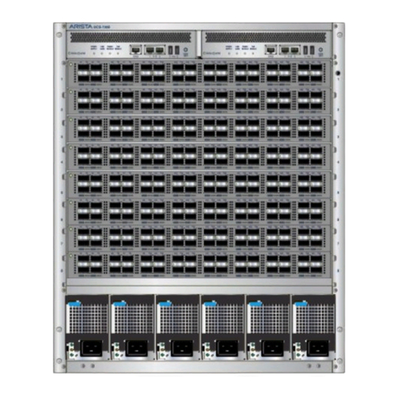
Page 25: Appendix C Front Panels
Appendix C: Front Panels Appendix C Front Panels This appendix displays the front panel of all switches covered by this guide. DCS-7304 Front Panel (fully populated) DCS-7308 Front Panel (fully populated) 7300 Series Modular Switch Quick Start Guide PDOC-00040-02... - Page 26 Appendix C: Front Panels DCS-7316 Front Panel (fully populated) Arista Networks Copyright 2014...
-
Page 27: Appendix D Rear Panel
Appendix D: Rear Panel Appendix D Rear Panel This appendix displays the rear panel of all switches covered by this guide. DCS-7304 Rear Panel DCS-7308 Rear Panel 7300 Series Modular Switch Quick Start Guide PDOC-00040-02... - Page 28 Appendix D: Rear Panel DCS-7316 Rear Panel Arista Networks Copyright 2014...
-
Page 29: Appendix E Linecards
Appendix E: Linecards Appendix E Linecards This appendix displays the linecards supported by modular switches covered by this guide. DCS-7300X-32Q-LC DCS-7300X-64S-LC DCS-7300X-64T-LC 7300 Series Modular Switch Quick Start Guide PDOC-00040-02... - Page 30 Appendix E: Linecards Arista Networks Copyright 2014...
Need help?
Do you have a question about the 7300 Series and is the answer not in the manual?
Questions and answers