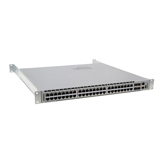
Receiving and Inspecting the Equipment • Installation Process • Safety Information • Obtaining Technical Assistance • Specifications Scope The following Arista Networks Data Center Switches are supported by this guide: DCS-7050SX-128 DCS-7250QX-64 DCS-7280QR-C72 DCS-7280CR3-96 DCS-7050TX-128 DCS-7260QX-64 DCS-7280CR-48 DCS-7280CR3K-96 DCS-7050SX2-128 DCS-7260CX-64...
Refer to the Arista Networks document Safety Information and Translated Safety Warnings available at: https://www.arista.com/en/support/product-documentation. Obtaining Technical Assistance Any customer, partner, reseller or distributor holding a valid Arista Service Contract can obtain technical support in any of the following ways: •...
Aucune pièce réparable par l'utilisateur à l'intérieur. Confiez toute réparation à un technicien qualifié. Specifications The following table lists the specifications of Arista Data Center switches covered by this guide. Table 1: Switch Specifications (Dimensions and Weights) Switch Size (W x H x D)
Page 9
Overview DCS-7250QX-64 / -48 to 60 VDC, 32 A PWR-1900DC DCS-7260CX-64 / -48 to 60 VDC, 46 A PWR-1900DC DCS-7260CX3-64 / -48 to 60 VDC, 32 A PWR-1900DC DCS-7260CX3-64E / -48 to 60 VDC, 32 A PWR-1900DC DCS-7280CR-48 / -48 to 60 VDC, 52 A PWR-1900DC DCS-7280CR2-60 / -48 to 60 VDC, 52 A...
Page 10
DCS-7280CR2A-60 1760 W / 1950 W DCS-7280CR2K-60 1760 W / 1950 W DCS-7170-64C 335 W / 585 W DCS-7280QR-C72 696 W / 1200 W DCS-7280CR3-96 1100 W / 1800 W DCS-7280CR3K-96 1100 W / 1800 W DCS-7050SX3-96YC8 218 W / 453 W...
Airflow Orientation: The fans and PSUs determine the airflow direction through the switch. The color of the visible handles or labels indicate the airflow direction. Note: The figures shown use representative Arista switches to illustrate airflow directions. For some switches, label color indicates the airflow direction.
Page 12
• Red Handle: Air Exit module. The following figure shows the airflow through the switch with air exit modules: Figure 2: Air Exit Module Orient the switch such that the airflow through the switch is from the cooler to the hotter aisle. If the airflow direction is not compatible with the installation site, reorient the fan modules to circulate air in the opposite direction.
Preparation Reconfiguring Air Flow Some switches allow configuration with either front-to-rear or rear-to-front airflow. To reconfigure a system, de-energize the unit and replace all fans and power supplies with the desired orientation. Mixing front-to-rear and rear-to-front components is not supported and will impact the cooling capacity of the switch.
Electrostatic Discharge (ESD) Precautions Observe these guidelines to avoid ESD damage when installing or servicing the switch. • Assemble or disassemble equipment only in a static-free work area. • Use a conductive work surface (such as an anti-static mat) to dissipate static charge. •...
Chapter 3 Rack Mounting the Switch The following topics are covered in this section: • Two-Post Rack Mount • Four-Post Rack Mount Important: The rack mounting procedure is identical for all switches covered by this guide. Illustrations in this chapter depict the mounting of a DCS-7050SX-128 switch. Les procédure de montage du bâti est identique pour tous les commutateurs visés par ce guide.
Bracket Mount Examples for Two-Post Rack Mount displays proper bracket mount configuration examples. Improper Bracket Mount Examples for Two-Post Rack Mount displays improper bracket mount configuration examples. Figure 3: Bracket Mount Examples for Two-Post Rack Mount Figure 4: Improper Bracket Mount Examples for Two-Post Rack Mount 3.1.1 Attaching Mounting Brackets to the Chassis This procedure attaches mounting brackets to the switch chassis...
Rack Mounting the Switch 1. Lift the chassis into the rack. Position the flanges against the rack posts. Figure 6: Inserting the Switch into the Rack 2. Select mounting screws that fit your equipment rack. 3. Attach the bracket flanges to the rack posts. After completing the two-post rack mount, proceed to Cabling the Switch.
Figure 7: Bracket Mount Examples for Four-Post Rack Mount displays proper bracket mount configuration examples. Figure 8: Improper Bracket Mount Example for Four-Post Rack Mount displays an improper bracket mount configuration examples. Figure 7: Bracket Mount Examples for Four-Post Rack Mount Figure 8: Improper Bracket Mount Example for Four-Post Rack Mount Off-set mount is always an improper bracket mount configuration on switches that have six attachment pins on each side.
Rack Mounting the Switch If the bracket flange resists initially, verify the thumb screw on the bracket flange is not attached to the rail flange. Figure 10: Extracting the Bracket-Rail Assembly 1 Inset A 5 Bracket flange 9 Inset B (detail) 2 Rail (Grip here) 6 Thumb screw 10 Locking clip...
To remove the mounting bracket from the chassis, lift the front edge of the mounting bracket clip with a flathead screwdriver and slide the bracket away from the front flange (opposite from the installation direction). Figure 12: Attaching the Mounting Brackets to the Switch Chassis 1 Bracket Clip 2 Bracket Clip 3.2.3...
Rack Mounting the Switch 2 Rail clip 4 Inset A 6 Rack plugs 3.2.4 Assembling the Rails onto the Equipment Rack A rail connects a front post to a rear post. Each end has two rack plugs (Attaching the Rails, Left-Inset 4Expanding the Rails - Right, Inset A).
Page 22
2. Slide the switch on the rails, toward the rear posts, until the mounting bracket flanges are flush with the rail flanges attached to the rack posts. Figure 15: Inserting the Switch onto the Rails 3. Attach the bracket flanges to the rack post using the quick-release thumb screws supplied with the brackets.
Chapter 4 Cabling the Switch • Grounding the Switch • Connecting Power Cables • Connecting Serial and Management Cables Grounding the Switch After mounting the switch into the rack, connect the switch to the data center ground. Important: Grounding wires and grounding lugs (M4 x 0.7) are not supplied. Wire size should meet local and national installation requirements.
Note: A representative 1 RU chassis is used for the illustrations to highlight the grounding adapter assembly and attachment. Figure 18: Earth Grounding Adapter for Models such as DCS-7050SX3-96YC8 4.1.3 Grounding Adapter Assembly Use the following steps to assemble and attach a grounding assembly to the chassis before mounting it into the rack for models that require the grounding adapter.
Cabling the Switch Connecting Power Cables Important: Installation of this equipment must comply with local and national electrical codes. If necessary, consult with the appropriate regulatory agencies and inspection authorities to ensure compliance. Installation de cet équipement doit être conformes aux codes électriques locaux et nationaux. Si nécessaire, consulter les organismes de réglementation appropriés et des autorités de contrôle pour assurer la conformité.
Figure 20: AC Power Supply displays an AC power supply, including the power socket on the left side of the module. Figure 20: AC Power Supply The accessory kit provides two IEC-320 power cables for the supported power supply for the device. 4.2.2 DC Power Supplies The following power supplies are supported.
Page 27
Cabling the Switch Important: Apply ground connection to the switch first during installation and remove last when removing power. Appliquer connexion à la terre à l'interrupteur premier lors de l'installation et de supprimer la dernière alimentation lors du débranchement. 4.2.2.1 Wire and Lug Preparation Before performing any installation actions, ensure power is removed from DC circuits by turning off the power line servicing the circuits.
6. Crimp the lugs with the proper tool, and ensure that the tubing extends over the barrel of the lugs and the insulation on the wires (Figure 22: Lug Preparation Figure 22: Lug Preparation 1 Insulated wire 3 Lug B 1/2” 2 Heat-shrink tubing A 1/4”...
Page 29
Cabling the Switch • RJ-45 to DB-9 serial adapter cable. • RJ-45 Ethernet cable. Table 6: RJ-45 to DB-9 Connections lists the pin connections of the RJ-45 to DB-9 adapter cable. Table 6: RJ-45 to DB-9 Connections RJ-45 DB-9 RJ-45 DB-9 The front panel contains the console, management, and USB ports.
Chapter 5 Configuring the Switch Arista switches ship from the factory in Zero Touch Provisioning (ZTP) mode. ZTP configures the switch without user intervention by downloading a startup configuration file or a boot script from a location specified by a DHCP server. To manually configure a switch, ZTP is bypassed. The initial configuration provides one username (admin) accessible only through the console port because it has no password.
Page 32
When the management port IP address is configured, use this command to access the switch from a host, using the address configured in step 9: ssh admin@192.0.2.8 Refer to the Arista Networks User Manual for complete switch configuration information.
Appendix A Status Indicators • Front Indicators • Switch Indicators • Port Indicators • Rear Status Indicators Front Indicators A.1.1 Switch Indicators Front panel LEDs are located on the right side of the chassis and display system, fan, and power supply status.
Power Supply 2 Status Green Power supply operating normally. Power supply has failed. Note: Arista fixed systems take approximately 5-10 minutes to boot completely. A.1.2 Port Indicators Port LEDs, located in the vicinity of their corresponding ports, provide link and operational status. Port Indicators displays the Port LED location on the DCS-7050SX-128 switch.
Status Indicators Rear Status Indicators Fan and power supply modules are accessed from the rear panel. Each fan and power supply module contains an LED that reports the module status. Rear Panel displays the rear panel of all switches covered by this guide. Fan Status LEDs are on the fan modules, as displayed in Figure 27: Fan Status LED.
Page 36
Table 10: Power Supply Status LED States provides status conditions that correspond to power supply status LED states. Table 10: Power Supply Status LED States LED State Status Power supply not connected to AC power or not inserted fully. Green Power supply operating normally.
Appendix B Parts List • Rack Mount Parts • Four-Post Rack Mount Parts • Two-Post Rack Mount Parts • Cables Each switch provides an accessory kit that contains parts that are required to install the switch. This appendix lists the installation parts contained in the switch accessory kit. Rack Mount Parts Four-post rack mount parts are provided in the accessory kit.
Cables Quantity Description Power cables: IEC-320/C13-C14, 13 A, 250 V, 2 meter RJ-45 Patch Panel Cable, 2 meter RJ-45 to DB9 Adapter Cable, 2 meter Warning: All provided power cables are for use only with Arista products.
Appendix C Front Panel This appendix displays the front panel of all switches covered by this guide. • Port-Speed Groups • Front Panels Port-Speed Groups Some of the devices shown in this appendix have ports that are grouped together to provide flexibility in configuring Ethernet speeds for the individual members of the group.
Page 40
Figure 32: DCS-7050TX-128 1 System status LED 4 Power supply 2 status LED 7 Ethernet management port 1 2 Fan tray status LED 5 Console serial port 8 Ethernet management port 2 3 Power supply 1 status LED 6 USB port 9 Port numbers Figure 33: DCS-7050SX2-128 1 System status LED...
Page 41
Front Panel Figure 34: DCS-7050TX2-128 1 System status LED 4 Power supply 2 status LED 7 Ethernet management port 1 2 Fan tray status LED 5 Console serial port 8 Ethernet management port 2 3 Power supply 1 status LED 6 USB port 9 Port numbers Figure 35: DCS-7250QX-64...
Page 42
Figure 36: DCS-7260QX-64 1 Ethernet management port 4 Power supply 1 status LED 7 Console serial port 2 System status LED 5 Power supply 2 status LED 8 Port numbers 3 Fan tray status LED 6 USB port Figure 37: DCS-7260CX-64 1 Ethernet management port 4 Power supply 1 status LED 7 Console serial port...
Page 43
Front Panel Figure 38: DCS-7260CX3-64 and DCS-7260CX3-64E 1 Ethernet management port 4 Power supply 1 status LED 7 Console serial port 2 System status LED 5 Power supply 2 status LED 8 Port numbers 3 Fan tray status LED 6 USB port Figure 39: DCS-7280CR-48 1 Ethernet management port 4 Power supply 1 status LED...
Page 44
Figure 40: DCS-7280CR2-60 1 Ethernet management port 4 Power supply 1 status LED 7 Console serial port 2 System status LED 5 Power supply 2 status LED 8 Port numbers 3 Fan tray status LED 6 USB port Figure 41: DCS-7280CR2A-60 1 Ethernet management port 4 Power supply 1 status LED 7 Console serial port...
Page 45
Front Panel Figure 42: DCS-7280CR2K-60 1 Ethernet management port 4 Power supply 1 status LED 7 Console serial port 2 System status LED 5 Power supply 2 status LED 8 Port numbers 3 Fan tray status LED 6 USB port Figure 43: DCS-7170-64C 1 Ethernet management port 4 Power supply 1 status LED...
Page 46
Figure 44: DCS-7280QR-C72 1 Ethernet management port 4 Power supply 1 status LED 7 Console serial port 2 System status LED 5 Power supply 2 status LED 8 Port numbers 3 Fan tray status LED 6 USB port There are twenty four port groups on the DCS-7280CR3-96. Groups are numbered sequentially from Group 1 (ports 1-4).
Page 47
Front Panel Figure 46: DCS-7050SX3-96YC8 1 Ethernet management port 4 Power supply 1 status LED 7 Console serial port 2 System status LED 5 Power supply 2 status LED 8 Port numbers 3 Fan tray status LED 6 USB port 9 Port groups...
Appendix D Rear Panel This appendix displays the rear panel of all switches covered by this guide. Depending on the power supply and fan modules installed, the rear panel on your switch may appear slightly different. Figure 47: Models Without Separation Between Fans 1 and 2 1 Fan Module 1 3 Fan Module 3 5 Power Supply Module 1...
Page 50
3 Fan Module 3 6 Power Supply Module 2 Figure 49: Models With Separation Between Fans 1 and 2 (no ground) 1 Fan Module 1 5 Fan Module 3 9 Release 2 Release 6 Fan Module 4 10 Power Supply Module 2 3 Status LED 7 Power Supply Module 1 4 Fan Module 2...
Appendix E Regulatory Model Numbers This appendix lists the Regulatory Model Numbers (RMNs) for the product models for the switches described in this document. Table 11: Regulatory Model Numbers and Product Numbers Regulatory Model Number (RMN) Product Name(s) DCS-7050SX-128 DCS-7050TX-128 DCS-7050SX2-128 DCS-7050TX2-128 DCS-7250QX-64...
Appendix F Taiwan RoHS Information This appendix provides Taiwan RoHS information for switches covered by this guide. For Taiwan BSMI RoHS Table, go to https://www.arista.com/assets/data/pdf/AristaBSMIRoHS.pdf.
Need help?
Do you have a question about the 7000 Series and is the answer not in the manual?
Questions and answers