Chapter 1 Overview Scope This guide is intended for properly trained service personnel and technicians who need to install Arista Networks Data Center Switches. This guide is intended for the following Arista Networks Data Center Switches: DCS-7304 DCS-7304X3 DCS-7308 DCS-7308X3...
Refer to the Arista Networks document Safety Information and Translated Safety Warnings available at: https://www.arista.com/en/support/product-documentation. Obtaining Technical Assistance Any customer, partner, reseller or distributor holding a valid Arista Service Contract can obtain technical support in any of the following ways: •...
5 to 90% Humidity Cooling 6000 W maximum 9000 W maximum 12000 W maximum Table 2: 7300 Series Power Specifications lists power specifications of modular switch components. Table 2: 7300 Series Power Specifications Module Type Part Number Power Draw Typical /...
Page 8
Linecard Modules DCS-7300X-32Q-LC 219 W / 372 W DCS-7300X-64S-LC 166 W / 232 W DCS-7300X-64T-LC 279 W / 430 W DCS-7320X-32C-LC 428 W / 516 W DCS-7300X3-32C-LC 284 W / 491 W DCS-7300X3-48YC4-LC 193 W / 228 W Fabric Modules DCS-7304X-FM 98 W / 172 W DCS-7308X-FM...
Page 9
Overview Table 3: 7300X Series lists 7300X Series switch components. Table 3: 7300X Series Chassis Fabric Fan-only Line Card Power Fan Spare Model Module Module Supply DCS-7304 DCS-7304X- DCS-7304-S- FAN-7002-F DCS-7300X- PWR-3K-AC- (Forward) FM-F FAN-F 32Q-LC DCS-7300X- PWR-2700- 64S-LC DC-F DCS-7300X- 64T-LC DCS-7304...
Page 10
DCS-7316 DCS-7316X- Not Available FAN-7002-R DCS-7300X- PWR-3K-AC- (Reverse) FM-R 32Q-LC DCS-7300X- PWR-2700- 64S-LC DC-F DCS-7300X- PWR-3K-AC- 64T-LC PWR-2700- DC-R Table 4: 7320X Series lists 7320X Series switch components. Table 4: 7320X Series Chassis Model Fabric Module Fan Spare Line Card Power Supply DCS-7324X DCS-7324X-FM-...
Page 11
16 A (20 A supply module 50 or 60 Hz supplied with switch. PWR-2700- DCS-7304 -48 to -60 100 A DC Adapter One DC Reverse DC-R (Arista part adapter (Red) DCS-7308 number per power PWR-2700- 80 A Forward DCS-7316 CON-00581) supply DC-F (Blue)
Page 12
Input power Vin Good Blinking present Amber, 0.5 DC Good sec on/off Supply not Fault Blinking seated in Green chassis...
Chapter 2 Preparation Site Selection Describes the location specifications. Consider the following criteria when selecting a site to install the switch: Floor Space:Install the switch in an area that provides adequate clearance for removing front and rear components. Thre following figure displays switch clearance requirements. Figure 1: Switch Component Removal Footprint 1.
When mounting the switch in a partially filled rack, load the rack from bottom to top, with the heaviest equipment at the bottom. Load the switch at the bottom if it is the only item in the rack. The accessory kit provides mounting brackets for four-post racks. Contact your sales representative to obtain two-post mounting racks.
Preparation Electrostatic Discharge (ESD) Precautions Observe these guidelines to avoid ESD damage when installing or servicing the switch. • Assemble or disassemble equipment only in a static-free work area. • Use a conductive work surfaces (such as an antistatic mat) to dissipate static charge. •...
Chapter 3 Rack Mounting the Switch Important: The rack mounting procedure is identical for all modular switches. Illustrations in this chapter depict the mounting of an unpopulated DCS-7304 chassis. Les procédure de montage du bâti est identique pour tous les commutateurs modulaires. Illustrations dans ce chapitre montrent le montage d’un châssis de DCS-7304 inhabité.
2. Attach both center-mount brackets to the chassis with the provided M4x8 panhead Phillips screws. Secure the bracket by attaching screws through each bracket hole. 3.1.2 Inserting the Switch into the Rack 1. Rotate the stabilizer bar from the left shelf toward the right shelf such that the nob at the end of the stabilizer bar inserts into the notch at the rear of the ledge of the right shelf.
Rack Mounting the Switch Four-Post Rack Mount The switch is mounted onto a four-post rack by assembling a shelf into the rack, then attaching the switch on the shelf. The four-post rack mount instructions include these sections: • Component Description •...
Page 20
Figure 6: Left Shelf – Inner View displays the inner view of the left shelf. Depending on the rack kit ordered, each shelf may include latches to the locking mechanism that secures the shelf to the rack. If the locking mechanism is not present, the kit shall be attached with appropriate screws (not included). Figure 6: Left Shelf –...
Rack Mounting the Switch Rack posts and guide pins that insert into the rack are visible from the outer side of the ear (Inset B). To install ears into posts with threaded or round holes, remove both plugs from each ear (if required for rail set), then install the ears with screws that fit the rack.
Page 22
1. Installing the shelves. 2. Installing the mounting ears. 3. Placing and securing the switch upon the shelves. 3.2.3.1 Shelf Installation The installation process for each shelf is identical. The shelves must be installed on the same horizontal level. In the following section, inner side illustrations feature the left shelf and outer side illustrations feature the right shelf.
Page 23
Rack Mounting the Switch Figure 11: Adjusting the Right Shelf Front left rack post Front right rack post Rear right rack post 5. Attach the back-side of the shelf into the rear shelf by gliding the slide-end such that the rack plugs (if present) and guide pins are inserted into the rack post holes (Figure 12: Seating the Left Shelf).
Page 24
1. Install the mounting ear on the front post by inserting the front rack plugs (if present) and guide pins in the racks specified for the switch model that is being installed (Figure 13: Attaching the Right Mounting Ear Figure 13: Attaching the Right Mounting Ear Front right rack post If rack plugs are not present, align the threaded holes and attach the mounting ears with screws.
Page 25
Rack Mounting the Switch 2. Move the chassis to the rack using a mechanical lift (Figure 4: Lifting the Switch Chassis). If modules are inserted in the chassis, use the lift carefully to avoid damaging any components. Figure 15: Lifting the Switch Chassis 3.
Table 8: Power Supply Capacity and Requirements for 7300 Series Modular Switches lists the quantity of modules each chassis can contain and the minimum operating requirements for each model. Table 8: Power Supply Capacity and Requirements for 7300 Series Modular Switches Switch Model Chassis Capacity Minimum Operating...
Cabling the AC Power Supply 4.1.1 Grounding the Switch After mounting the switch into the rack, connect the switch to the data center ground. Figure 16: Grounding Pad and ESD Grounding Pad Sockets displays the location of the grounding pads located on the front panel (left illustration) and rear panel (right illustration).
Le - 48V et câbles de batterie-retour sont une paire courir à côté de l'autre et doivent être à peu près la même longueur. 4.2.1 DC Power Supplies The 7300 Series chassis supports two DC power supplies (Figure 4-4). Only specified power supplies are available for use in a particular switch configuration.
Figure 18: Secondary Ground Pads Secondary ground Secondary ground Earth grounding pad Note: The power supply orientation in your device may be different from the one shown Figure 19: PWR-3K-DC-Blue and PWR-2700-DC-R Power Supplies Figure 19: PWR-3K-DC-Blue and PWR-2700-DC-R Power Supplies Primary ground 4.2.2 Wire and Lug Preparation...
Page 31
Powering the Modular Switch • Commercially available 2 to 4 AWG wire is recommended for installations in the U.S. • Wire size should meet local and national installation requirements. • Grounding wires and grounding lugs are not supplied. • Strip the wires to the appropriate length for the lugs. The wires connecting the DC power supply to the power source must meet the following requirements: •...
4.2.3 PWR-3K-DC-Blue Power Supply Figure 22: PWR-3K-DC-Blue Power Supply displays the PWR-3K-DC-Blue power supply. Figure 22: PWR-3K-DC-Blue Power Supply 1. Prepare the stranded wiring, see Wire and Lug Preparation 2. Attach the power cable to the supply terminals. 3. Tightening Torque: 2.7 N-m (24 in.-lbs.) DC Power Adapter Installation for PWR-2700-DC-R 4.3.1 Connecting the Power Cable Lug to the Terminal Studs...
Page 33
Powering the Modular Switch Primary ground Figure 23: PWR-2700-DC-R Power Supply 1. Prepare the stranded wiring, see Section 4.2.2. 2. Attach the ground cable to the ground stud. 3. Tightening Torque: 2.7 N-m (24 in.-lbs.).
Connecting Serial and Management Cables Connecting Supervisor Cables Supervisor modules contain console, management, and USB ports. Figure 24: Supervisor Ports (DCS-7300(-D)-SUP) displays status LED and port locations on 7300 Series Modular switch supervisor. Figure 24: Supervisor Ports (DCS-7300(-D)-SUP) Status LED Fabric module status...
Connecting Linecard Modules and Cables Install required SFP, SFP+, and QSFP+ optic modules in linecard module ports (Figure 25: SFP or SFP+ Ports Connect cables as required to linecard module ports or RJ45 ports. Figure 25: SFP or SFP+ Ports CAUTION: Excessive bending can damage interface cables, especially optical cables.
Chapter 6 Configuring the Switch Arista switches ship from the factory in Zero Touch Provisioning (ZTP) mode. ZTP configures the switch without user intervention by downloading a startup configuration file or a boot script from a location specified by a DHCP server. To manually configure a switch, ZTP is bypassed. The initial configuration provides one username (admin) accessible only through the console port because it has no password.
Page 38
11. When the management port IP address is configured, use this command to access the switch from a host, using the address configured in Step ssh admin@192.0.2.8 Refer to the Arista Networks User Manual for complete switch configuration information.
Appendix A Status Indicators This section discusses the several status indicators, their location, and the meaning of their display status. Supervisor Module While the front panel of each switch can house two supervisors, switch operations require only one. Supervisors display switch component status and contain Ethernet management and console ports. Fabric and Fan-only Module Description displays the supervisor location on each switch.
Status Module failed or is improperly inserted. Green Supervisor operating normally. Module failed. Active Supervisor is not active. Green Supervisor is active and controlling the switch. Component Activity Status LEDs LEDs located below the vents and left of the input ports display summary indicators for power supplies, fabric modules, fan modules, and line cards.
Page 41
Status Indicators Figure 27: Linecard Status LEDs (DCS-7300X-LC) Status LED Upper port status LED Lower port status LED Figure 28: Linecard Status LEDs (DCS-7300X-32Q-LC) Status LED QSFP 2 10G/40G QSFP Port QSFP 3 LEDs QSFP 1 QSFP 4 The Line Card Status LED is in the top left corner of the DCS-7300X Line Card. Table 11: Line Card Status LED States interprets the states of the Status LED.
Line card not inserted. Green Line card operating normally. Yellow Line card administratively shut down. Module has failed. The Line card provides LEDs for each port module socket: • Figure 27: Linecard Status LEDs (DCS-7300X-LC) displays SFP module LEDs. Each LED corresponds to a module.
Status Indicators Figure 29: Fan Status and Fabric Status LEDs Handle (color indicates Fan module installation airflow orientation) indicator Fabric status LED Fan module status LED The fan module installation indicator is green when the fan module is properly installed or red when the module is not fully installed.
Page 44
Figure 30: Power Supply Release DC OK LED AC OK LED Ejector (color indicates Fault LED airflow orientation) Table 15: Power Supply Status interprets the states of the Power Supply Status LED. Table 15: Power Supply Status AC OK LED Fault LED DC OK LED Status...
Appendix B Fabric and Fan-only Module Description Each switch has four rear slots for fabric modules. In addition to providing the data transport media, fabric modules contain fan modules that circulate air through the switch. Proper switch operation requires the population of each rear slot. Switches that are configured for maximum traffic capacity contain a fabric module in each rear slot.
Metal covering Part Numbers Table 16: Fabric and Fan-only Module Part Numbers lists the part numbers of Fabric and Fan-only Modules. Table 16: Fabric and Fan-only Module Part Numbers Switch Model Fabric Module Fan-only Module DCS-7304 (Air Inlet) DCS-7304X-FM-R DCS-7304-S-FAN-R DCS-7304 (Air Exit) DCS-7304X-FM-F DCS-7304-S-FAN-F...
Figure 33: Fabric Module Removal: Initial Position and Opening the Lock-Levers Figure 34: Fabric Module Removal: Edging the Module Out and Closing the Lock-Levers The DCS-7316 fabric module is almost three feet long and weighs close to 40 pounds. Use necessary precautions to safely manage the component outside of the chassis.
Fabric and Fan-only Module Description 5. Return the lock-levers to the closed position, securing the module to the chassis (Fabric Module- left). Handling Fan-only Modules DCS-7304 Fabric and Fan-only Module (left) depicts a DCS-7304 chassis with installed fabric modules (slots 1 and 2) and fan-only modules (slots 3 and 4). Lock-levers are shown in the open (slot 3) and closed (slot 4) position DCS-7304 Fan-only Module (right) displays the position of the lock lever...
B.2.2 Inserting Fan-only Modules The fabric module insertion process is the inverse of the removal procedure. These instructions describe the method of inserting the fabric module into a chassis. 1. Grasping the module by its frame, place the module chassis railing that corresponds to the slot where it is to be placed.
), Terminal Block, M4 Lug. RJ-45 Patch Panel Cables, 2 meters. RJ-45 to DB9 Adapter Cable, 2 meters. Warning: All provided power cables are for use only with Arista products. Figure 36: DC Adapter Four-Post Rack Mount Parts Quantity Description...
Right shelf Figure 37: Four-Post Rack Mount Parts Left shelf Right shelf Mounting ears Four-Post Rack Mount Kit (Optional - 106-575-074-00) Part Number Quantity Description Rack Type 036-030-014 M610 clip nuts Round hole 036-023-025 M6 cage nuts Square hole 036-020-051 12-24 x .50 screws Threaded hole 106002508...
Page 53
Parts List 16 (DCS-7304) M4x8 panhead Phillips screws. 20 (DCS-7308) Figure 38: Two-Post Rack Mount Parts
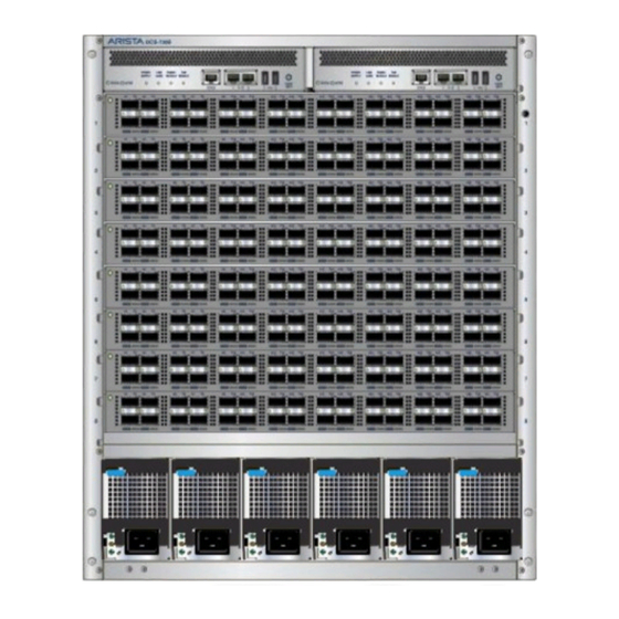
 Center-mount brackets M4x8 panhead Phillip (7308 only) Screws Center-mount brackets (7304 only)
Appendix D Front Panels This Front Panel section displays the front panel of all switches covered by this guide. DCS-7304 and DCS-7324 Front Panel (fully populated) Supervisor modules (slots 1-2) Linecard modules (slots 3-6) Power supply modules Earth grounding pads (behind covers)
Page 56
DCS-7308 and DCS-7328 Front Panel (fully populated) Supervisor modules (slots 1-2) Linecard modules (slots 3-10) Power supply modules Earth grounding pads (behind covers)
Page 57
Front Panels DCS-7316 Front Panel (fully populated) ESD grounding port Linecard modules (slots 3-10) Supervisor modules (slots 1-2) Linecard modules (slots 11-18) Power supply modules...
Appendix E Rear Panels This Rear panel section displays the rear panel of all switches covered by this guide. DCS-7304 and DCS-7324 Rear Panel ESD grounding port Fabric modules Fan modules...
Page 60
DCS-7308 and DCS-7328 Rear Panel ESD grounding port Fabric modules Fan modules...
Page 61
Rear Panels DCS-7316 Rear Panel ESD grounding port Fabric modules Fan modules Power Supply Modules...
Appendix F Line Cards This Line Card section displays the Line cards supported by modular switches covered by this guide. DCS-7300X-32Q-LC Status LED 10G/40G port LEDs DCS-7300X-64S-LC Status LED 10G/40G Port LEDs 10G upper port LEDs 10G lower port LEDs DCS-7300X-64T-LC Status LED 10G/40G Port LEDs...
Page 64
DCS-7320X-32C-LC and DCS-7300X3-32C-LC Status LED 100G port LEDs DCS-7300X3-48YC4-LC Status LED QSFP 100G port LEDs SFP 25G port LEDs SFP 25G port LEDs...
Appendix G Taiwan RoHS Information This section provides Taiwan RoHS information for switches covered by this guide. For Taiwan BSMI RoHS Table, go to https://www.arista.com/assets/data/pdf/AristaBSMIRoHS.pdf.
Need help?
Do you have a question about the 7300 Series and is the answer not in the manual?
Questions and answers