Arista 7000 Series Quick Start Manual
Tool-less data center switches 1 ru gen 3
Hide thumbs
Also See for 7000 Series:
- Quick start manual (54 pages) ,
- Quick start manual (34 pages) ,
- Quick start manual (40 pages)
Table of Contents
Advertisement
Advertisement
Table of Contents

Related Manuals for Arista 7000 Series


Summary of Contents for Arista 7000 Series
-
Page 1: Quick Start Guide
Quick Start Guide 7000 Series 1 RU – Gen 3 Data Center Switches (Tool-less) DCS-7050QX-32S DCS-7050TX-72 DCS-7050SX-64 DCS-7050TX-96 DCS-7050SX-72 DCS-7280SE-64 DCS-7050SX-96 DCS-7280SE-68 DCS-7050TX-48 DCS-7280SE-72 DCS-7050TX-64 DCS-7050QX2-32S Arista Networks www.arista.com PDOC-00041-07... -
Page 2: Arista Networks
© Copyright 2015 Arista Networks, Inc. The information contained herein is subject to change without notice. Arista Networks and the Arista logo are trademarks of Arista Networks, Inc in the United States and other countries. Other product or service names... -
Page 3: Chapter 1 Overview
Important! Ultimate disposal of this product should be in accordance with all applicable laws and regulations. Safety Information Refer to the Arista Networks document Safety Information and Translated Safety Warnings available at: http://www.arista.com/en/support/docs/eos 7000 Series 1 RU – Gen 3 Quick Start Guide... -
Page 4: Obtaining Technical Assistance
Chapter 1: Overview Obtaining Technical Assistance Any customer, partner, reseller or distributor holding a valid Arista Service Contract can obtain technical support in any of the following ways: • Email: support@arista.com. This is the easiest way to create a new service request. -
Page 5: Chapter 2 Preparation
When mounting the switch in a partially filled rack, load the rack from bottom to top, with the heaviest equipment at the bottom. Load the switch at the bottom if it is the only item in the rack. 7000 Series 1 RU – Gen 3 Quick Start Guide PDOC-00041-06... -
Page 6: Tools Required For Installation
Minimize handling of assemblies and components. • Keep replacement parts in their original static-free packaging. • Remove all plastic, foam, vinyl, paper, and other static-generating materials from the work area. • Use tools that do not create ESD. Arista Networks Copyright 2014... -
Page 7: Chapter 3 Rack Mounting The Switch
Front bracket hole does not lock into pin Rear bracket hole does not lock into pin Figure 3: Improper Bracket Mount Examples for Two-Post Rack Mount 7000 Series 1 RU – Gen 3 Quick Start Guide PDOC-00041-06 PDOC-00041-07... - Page 8 Figure 5: Inserting the Switch into the Rack Step 2 Select mounting screws that fit your equipment rack. Step 3 Attach the bracket flanges to the rack posts. After completing the two-post rack mount, proceed to Chapter 4: Cabling the Switch. Arista Networks Copyright 2014...
-
Page 9: Four-Post Rack Mount
Figure 6: Bracket Mount Examples for Four-Post Rack Mount Figure 7 displays an improper bracket mount configuration example. Bracket not attached by at least 5 pins Figure 7: Improper Bracket Mount Example for Four-Post Rack Mount 7000 Series 1 RU – Gen 3 Quick Start Guide PDOC-00041-06 PDOC-00041-07... - Page 10 Figure 9: Attaching the Mounting Brackets to the Switch Chassis To remove the mounting bracket from the chassis, lift the front edge of the mounting bracket clip with a flathead screwdriver and slide the bracket away from the front flange (opposite from the installation direction). Arista Networks Copyright 2014...
- Page 11 Step 4 Repeat step 1 through step 3 for the left posts. Ensure the rails are on the same horizontal level. Inset A Inset B Inset B Inset A Figure 11: Attaching the Rails 7000 Series 1 RU – Gen 3 Quick Start Guide PDOC-00041-06 PDOC-00041-07...
- Page 12 Step 3 Attach the bracket flanges to the rack post using the quick-release thumb screws supplied with the brackets. Figure 13: Attaching the Switch to the Rack Posts After completing the four-post rack mount, proceed to Chapter 4: Cabling the Switch. Arista Networks Copyright 2014...
-
Page 13: Chapter 4 Cabling The Switch
Figure 15: AC Power Supply The power supplies require power cables that comply with IEC-320 and have a C13 plug. The accessory kit provides two IEC-320 C13 to C14 power cables. 7000 Series 1 RU – Gen 3 Quick Start Guide PDOC-00041-06 PDOC-00041-07... -
Page 14: Connecting Serial And Management Cables
Ethernet Management Port: Connect to 10/100/1000 management network with RJ-45 Ethernet cable. • USB Port: The USB port may be used for software or configuration updates. Caution Excessive bending can damage interface cables, especially optical cables. Arista Networks Copyright 2014... -
Page 15: Chapter 5 Configuring The Switch
Chapter 5: Configuring the Switch Chapter 5 Configuring the Switch Arista switches ship from the factory in Zero Touch Provisioning (ZTP) mode. ZTP configures the switch without user intervention by downloading a startup configuration file or a boot script from a location specified by a DHCP server. - Page 16 Chapter 5: Configuring the Switch Arista Networks Copyright 2014...
-
Page 17: Appendix A Status Indicators
Figure 17 displays the DCS-7050QX-32S front panel LEDs. System Status LED Fan Status LED Power Supply 1 Status LED Power Supply 2 Status LED Figure 17: System Status Indicators 7000 Series 1 RU – Gen 3 Quick Start Guide PDOC-00041-06 PDOC-00041-07... - Page 18 In order to narrow down the specific condition, you must login to the switch to view the specific device state. Refer to the Arista User Manual’s Switch Environment Control chapter, under the topic Viewing Environment Status, the for further information on the show environment commands.
-
Page 19: Port Indicators
SFP+ ports is consistent. Table 4: Port LED States LED State Status Port link is down. Green Port link is up. Yellow Port is software disabled. Flashing Yellow Port failed diagnostics. 7000 Series 1 RU – Gen 3 Quick Start Guide PDOC-00041-06 PDOC-00041-07... - Page 20 LED states. Table 6: Power Supply Status LED States LED State Status Power supply not connected to AC power or not inserted fully. Green Power supply operating normally. Amber Power supply has overheated or failed. Arista Networks Copyright 2014...
-
Page 21: Appendix B Parts List
Description Power cables: IEC-320/C13-C14, 13 A, 250 V RJ-45 Patch Panel Cable RJ-45 to DB9 Adapter Cable Warning! All provided power cables are for use only with Arista products. 警告 すべての電源コードは提供する製品で使⽤するためだけを⽬的としている。 電源コードの他の製品での使⽤の禁⽌ Arista が提供するすべての電源コードは、Arista の製品でのみ使⽤してください。 7000 Series 1 RU – Gen 3 Quick Start Guide... -
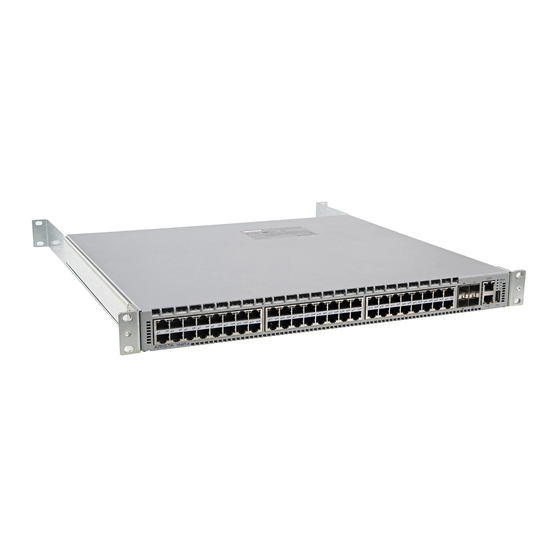
Page 22: Appendix C Front Panel
Figure 24: DCS-7050SX-64 Front Panel DCS-7050SX-72 Fan Tray Status LED System Status LED Console (Serial) Port 7050SX-72 Ethernet Management Port USB Flash Port Power Supply 2 Status LED Power Supply 1 Status LED Figure 25: DCS-7050SX-72 Front Panel Arista Networks Copyright 2014... -
Page 23: Dcs-7050Tx
Fan Tray Status LED System Status LED Console (Serial) Port Ethernet Management Port USB Flash Port Power Supply 2 Status LED Power Supply 1 Status LED Figure 28: DCS-7050TX-64 Front Panel 7000 Series 1 RU – Gen 3 Quick Start Guide PDOC-00041-06 PDOC-00041-07... - Page 24 Figure 30: DCS-7050TX-96 Front Panel DCS-7280SE-64 Fan Tray Status LED System Status LED Console (Serial) Port Ethernet Management Port USB Flash Port Power Supply 2 Status LED Power Supply 1 Status LED Figure 31: DCS-7280SE-64 Front Panel Arista Networks Copyright 2014...
-
Page 25: Dcs-7280Se
Fan Tray Status LED System Status LED Console (Serial) Port Ethernet Management Port USB Flash Port Power Supply 2 Status LED Power Supply 1 Status LED Figure 33: DCS-7280SE-72 Front Panel 7000 Series 1 RU – Gen 3 Quick Start Guide PDOC-00041-06 PDOC-00041-07... -
Page 26: Appendix D Rear Panel
Fan Module Fan Module Fan Module Fan Module Airflow Direction Power Supply Handle Handle Handle Handle Power Supply Module 1 Module 1 Module 2 Module 3 Module 4 Module 2 Earth Grounding Port Figure 34: Rear Panel Arista Networks Copyright 2014...
Need help?
Do you have a question about the 7000 Series and is the answer not in the manual?
Questions and answers