
Related Manuals for Arista 7388X5 Series


Summary of Contents for Arista 7388X5 Series
- Page 1 RISL Quick Start Guide 7388X5 Series Modular Data Center Switches Arista Networks www.arista.com DOC-05054-02...
- Page 2 The trademarks, logos and service marks ("Marks") displayed in this documentation are the property of Arista Networks in the United States and other countries. Use of the Marks are subject to Arista Network Term of Use Policy, available at http://www.arista.com/en/terms...
-
Page 3: Table Of Contents
Contents Chapter 1: Overview................1 1.1 Scope..........................1 1.2 Receiving and Inspecting the Equipment................1 1.3 Installation Process......................1 1.4 Safety Information.......................1 1.5 Obtaining Technical Assistance..................2 1.6 Specifications........................3 Chapter 2: Preparation................. 5 2.1 Site Selection........................5 2.2 Tools Required for Installation.................... 6 2.3 Electrostatic Discharge (ESD) Precautions................ - Page 4 Contents Appendix C: Front Panels..............33 Appendix D: Rear Panels..............35 Appendix E: Line Cards..............37 Appendix F: Maintenance and Field Replacement......39 F.1 Switch Card Module......................39 F.1.1 Removing Switch Card Module................39 F.1.2 Inserting Switch Card Module................39 F.2 Power Supplies......................... 40 F.2.1 Removing a Power Supply..................40 F.2.2 Installing a Power Supply..................41 F.3 Fan Modules........................41 F.3.1 Removing a Fan Module..................
-
Page 5: Chapter 1: Overview
Cables. Configuring the Switch. Safety Information Refer to the Arista Networks document Safety Information and Translated Safety Warnings available at: https://www.arista.com/en/support/product-documentation. Important: Class 1 Laser Product: This product has provisions to install Class 1 laser transceivers that provides optical coupling to the communication network. Once a Class 1 laser product is installed, the equipment is a Class 1 Laser Product (Appareil à... -
Page 6: Obtaining Technical Assistance
The fabric module requires special handling when removing, inserting, or handling the component. Appendix F provides instructions for handing fabric modules. Obtaining Technical Assistance Any customer, partner, reseller or distributor holding a valid Arista Service Contract can obtain technical support in any of the following ways: •... -
Page 7: Specifications
Overview Specifications The following table lists specifications of Arista Data Center modular switches and components covered by this guide. Table 1: DCS-7388X5 Modular Switch and Component Specifications Attribute Specification Height 4 RU: 174 mm (7.0 inches) Width 440 mm (17.3 inches) Depth 680 mm (26.8 inches) - Page 8 Table 2: 7388 Modular Switch and Component Power Specifications Module Type Part Number Power Draw: Typical / Maximum Supervisor DCS-7388-SUP, DCS-7388- 33 W / 53 W SUP-D Linecard DCS-7388-16CD, 2.2 W / 4.4 W DCS-7388-16CD2 DCS-7388-8DR 17 W / 39 W DCS-7388-8D 142 W / 161 W...
-
Page 9: Chapter 2: Preparation
Chapter 2 Preparation Site Selection The following criteria should be considered when selecting a site to install the switch: Floor Space: Install the switch in an area that provides adequate clearance for removing front and rear components.The following diagram provides switch clearance requirements. Figure 1: Switch Component Removal Footprint Table 3: Clearance requirements and footprint dimensions Dimension... -
Page 10: Tools Required For Installation
The accessory kit provides mounting brackets for four-post racks. Two-post mounting racks are not supported. Important: All power input plug-socket combinations must be accessible at all times; they provide the primary method of disconnecting power from the system. Toutes les combinaisons de fiche-prise d’entrée de puissance doivent être accessibles en tout temps;... - Page 11 Preparation • Minimize handling of assemblies and components. • Keep replacement parts in their original static-free packaging. • Remove all plastic, foam, vinyl, paper, and other static-generating materials from the work area. • Use tools that do not create ESD.
-
Page 13: Chapter 3: Rack Mounting The Switch
Chapter 3 Rack Mounting the Switch The switch must be mounted in a four-post rack. Perform the following tasks to mount the switch. • Attach the left and right shelf to the rack, adjusting the length of the shelves as needed. You must allocate 4RU rack space starting from the top of the shelf for switch placement (Shelf Installation). -
Page 14: Mounting Ears Installation
Note: You must ensure that the shelves are installed at the same level in the rack. Figure 3: Adjusting Shelves to Fit onto the Rack (Right Shelf Shown) Figure 4: Switch Shelves Installed Mounting Ears Installation The following figure shows the rack mounting ears, which secure the switch top to the rack. Attach the two rack mounting ears to each side of the switch. - Page 15 Rack Mounting the Switch Note: The rack mounting ears use only the top two rack units but you must allocate four rack units from the top of the shelves for the switch. Figure 6: Inserting the Switch Figure 7: Securing the Switch...
-
Page 17: Chapter 4: Powering The Modular Switch
Installation de cet équipement doit être conformes aux codes électriques locaux et nationaux. Si nécessaire, consulter les organismes de réglementation appropriés et des autorités de contrôle pour assurer la conformité. Table 4: Power Supply Capacity and Requirements for 7388X5 Series Modular Switches Switch Model Chassis Capacity... - Page 18 Cet équipement doit être mis à la terre. Ne jamais modifier le conducteur de terre. Cet appareil nécessite de protection contre les surintensités.
-
Page 19: Cabling The Ac Power Supply
Powering the Modular Switch Cabling the AC Power Supply 4.1.1 Grounding the Switch After mounting the switch into the rack, connect the switch to the data center ground. The following figure displays the location of the grounding pads located on the rear of the switch. Figure 8: Grounding location and ESD attach points (rear) 1 Switch Card Module 4 Fan Module Release... -
Page 20: Connecting Power Cables To An Ac Power Supply
After the switch is grounded, ESD wrist straps can be grounded by connecting them to the ESD port on the front of the switch. Figure 9: Grounding location and ESD attach point (Front) 1 ESD attach point 3 Supervisor and Linecard 5 Pull Tag (for Switch Ejector Handle (Release) Information) -
Page 21: Dc Power Supplies
Powering the Modular Switch DC Power Supplies The following DC power supplies are supported. • PWR-2411-DC-RED • PWR-2421-HV The following image displays the DC power supply. Figure 11: DC Power Supply Examples 1 Power Supply Status LED 4 RTN (Battery return) 7 Plastic Cover Terminal 2 -48V Terminal... -
Page 22: Connecting A Dc Power Supply To Power Source
2. Prepare the stranded copper wiring for the power supply to be used. The following table provides wiring, lug, and tightening torque information for the power supplies covered in this guide. Table 5: Wiring, Lug, and Tightening Torques for DC PSUs Wire Size Tightening Torque Lug Type... - Page 23 Powering the Modular Switch Note: The ground (protective earth) terminal is on the opposite side from the other two terminals.
-
Page 25: Chapter 5: Connecting Serial And Management Cables
Chapter 5 Connecting Serial and Management Cables Connecting Supervisor Cables Supervisor module contains the console, management, and USB ports. The following figure displays port locations on DCS-7388-SUP-D supervisor. Figure 13: Supervisor Ports 1 USB Port 3 Ethernet Management Port 5 Torque Clutch Tool (shared by Supervisor and Linecards) 2 Console Port (Serial) -
Page 26: Connecting Linecard Modules And Cables
Note: In some devices, adjacent QSFP ports may require you to rotate the module for insertion. Figure 14: Optical Module Insertion (representative) Note: For more information about supported optical transceivers, refer to https:// www.arista.com/assets/data/pdf/Transceiver-Guide-V04.pdf. Note: Excessive bending can damage interface cables, especially optical cables. -
Page 27: Chapter 6: Configuring The Switch
Chapter 6 Configuring the Switch Arista switches ship from the factory in Zero Touch Provisioning (ZTP) mode. ZTP configures the switch without user intervention by downloading a startup configuration file or a boot script from a location specified by a DHCP server. - Page 28 When the management port IP address is configured, use this command to access the switch from a host, using the address configured in step 9: ssh admin@192.0.2.8 Refer to the Arista Networks User Manual for complete switch configuration information.
-
Page 29: Appendix A: Status Indicators
Appendix A Status Indicators Supervisor Module Status Indicators The supervisor displays switch component status and contains Ethernet management and console ports. The supervisor location is on the Front Panels of the switch. The supervisor provides one serial console port, one Ethernet management port, and one USB port. Four LEDs on the top edge report system status, fan status, power status, and switch module status. -
Page 30: Linecard Module Indicators
Table 6: Supervisor LED States LED Name LED State Module State Power Supply Green All powered modules are operating normally. At least one module has failed. System Green All linecards are operating normally. At least one linecard has failed. Switch Card Green Module is operating normally. -
Page 31: Fan Module Status Indicators
Status Indicators 1 Linecard 3 Linecard Status LED 5 Port Status LEDs 2 Linecard Ejector 4 Linecard Ports (Release) Handle The Linecard Status LED is in the center of the DCS-7388-16CD. The following tables interpret the states of the Status LED and the port LED. Table 7: Linecard Status LED States LED State Status... - Page 32 Note: The orientation of the fan module as inserted in the switch may be different from the one shown. Figure 17: Fan status LEDs 1 Fan Airflow Direction 3 Fan Status LED Indicator Bezel Color 2 Fan Release Handle The following table interprets the states of the Fan Status LED. Table 10: Fan and switch card LED States LED State Status...
-
Page 33: Power Supply Status Indicators
Status Indicators Power Supply Status Indicators Power Supply LEDs are on power supply modules. The power supply modules for all switches are accessible from the Rear Panels of the switch. The following figure displays a power supply module. The power supply handle indicates the power supply airflow direction. Verify the airflow direction of all fan and power modules. -
Page 35: Appendix B: Parts List
Power cables: TBD One for each AC power supply module supplied with switch RJ-45 Patch Panel Cables, 2 meters. RJ-45 to DB9 Adapter Cable, 2 meters. Note: All provided power cables are for use only with Arista products. Four-Post Rack Mount Parts... - Page 36 Table 13: Four-Post Rack Mount Parts Quantity Description Mounting Ears Left shelf Right shelf Figure 19: Four-Post Rack Mount Parts 1 Left Shelf 2 Right Shelf...
-
Page 37: Appendix C: Front Panels
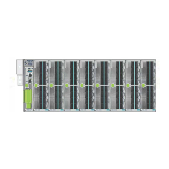
Appendix C Front Panels The following illustration displays the front panel of all switches covered by this guide. Figure 20: DCS-7388X5 Front Panel (fully populated) 1 ESD Attach Point 3 Supervisor and Linecard 5 Pull Tag (for Switch Ejector Handle (Release) Information) and Latch Indicator Button 2 Supervisor Module... -
Page 39: Appendix D: Rear Panels
Appendix D Rear Panels The following illustration displays the rear panel of all switches covered by this guide. Figure 21: DCS-7388X5 Rear Panel 1 Switch Card Module 4 Fan Module Release 7 PSU Release Release Handle 2 Switch Card Module 5 Fan Status LED 8 PSU Release Buttons... -
Page 41: Appendix E: Line Cards
Appendix E Line Cards The following illustrations display the Linecards supported by modular switches covered by this guide. Figure 22: DCS-7388-16CD and DCS-7388-16CD2 1 Linecard 3 Linecard Status LED 5 Port Status LEDs 2 Linecard Ejector 4 Linecard Ports (Release) Handle... - Page 42 Figure 23: DCS-7388-8D and DCS-7388-8DR 1 Linecard 3 Linecard Status LED 5 Port Status LEDs 2 Linecard Ejector 4 Linecard Ports (Release) Handle...
-
Page 43: Appendix F: Maintenance And Field Replacement
Appendix F Maintenance and Field Replacement There is a linecard and supervisor removal tool to facilitate the removal and installation of linecards and supervisor modules. Use the tool as a sleeve on the release handle. It is mounted on the supervisor module Front Panels. -
Page 44: Power Supplies
Note: The module will stop sbout 8 mm (1/3") from the back of the switch. 3. Close the release handle (swing arm) to its locked position (up) until both the green buttons pop out. Note: The upward swing arm movement will push and seat the switch card module. The green buttons pop out to indicate that the switch card module is locked. -
Page 45: Installing A Power Supply
Maintenance and Field Replacement F.2.2 Installing a Power Supply You must make space for installing the power supply by removing an existing one (Removing a Power Supply). 1. Remove the replacement power supply from its packaging. 2. Slide the new power supply into the empty slot. 3. -
Page 46: Installing A Fan Module
2. Pinch the fan module release lever and slide the fan module out of the switch as shown in the figure below. Figure 26: Removing fan module Note: Fans are hot swappable and do not require the removal of the switchcard. The illustration shows the switchcard removed for clarity. -
Page 47: Installing Supervisor Module
Maintenance and Field Replacement 3. Push in the latch indicator button. Note: The handle will rotate freely without loosening the supervisor module if the latch indicator button is not pushed in. 4. Attach the removal tool to the supervisor module ejector handle. 5. -
Page 48: Removing Linecard
Note: A representative linecard is shown for illustration. Figure 27: Linecard Module Maintenance 1 Linecard Metal 3 Latch Indicator Button 5 Linecard Metal 2 Ejector (Release) Handle 4 Engaging and Aligning, Geared Screw F.5.1 Removing Linecard Perform the following steps to remove a linecard. 1. -
Page 49: Installing Linecard
Note: The latch indicator button pops out and the tool rotates freely when the linecard is fully seated. Note: Hand tightening is sufficient for installation. 7. Verify that the linecard is operating normally (Linecard Module Indicators). Optical Transceivers For more information about supported optical transceivers and how to remove or install them, refer to https://www.arista.com/assets/data/pdf/Transceiver-Guide-V04.pdf. -
Page 51: Appendix G: Regulatory Model Numbers
Appendix G Regulatory Model Numbers The following table lists the regulatory model numbers (RMNs), where applicable, for the product models for the switches described in this document. Table 14: Regulatory Model Numbers and Product Numbers Regulatory Model Number (RMN) Product Number(s) DCS-7388 DCS-7388X5... -
Page 53: Appendix H: Taiwan Rohs Information
Appendix H Taiwan RoHS Information The following link provides Taiwan RoHS information for switches covered by this guide. For Taiwan BSMI RoHS Table, go to https://www.arista.com/assets/data/pdf/AristaBSMIRoHS.pdf.
Need help?
Do you have a question about the 7388X5 Series and is the answer not in the manual?
Questions and answers