
Related Manuals for Arista 7020SR-32C2 Series


Summary of Contents for Arista 7020SR-32C2 Series
- Page 1 Quick Start Guide 7020SR-32C2 Series 1 RU (Gen 3) Data Center Switches Arista Networks www.arista.com DOC-00152-01...
- Page 2 © Copyright 2019 Arista Networks, Inc. The information contained herein is subject to change without notice. Arista Networks and the Arista logo are trademarks of Arista Networks, Inc in the United States and other countries. Other product or service names may be trademarks or service marks of others.
-
Page 3: Table Of Contents
Status Indicator LEDs...................21 System-level Status Indicator LEDs...................... 21 A.1.1 System Status Indicator LED ....................21 A.1.2 Fan Status Indicator LED......................21 A.1.3 Port Status Indicator LEDs....................... 22 Component Status Indicators........................ 22 Quick Start Guide: 7020SR-32C2 Series 1 RU-Gen 3 Data Center Switches... - Page 4 Installing a Power Supply......................31 Fan Modules ............................32 E.3.1 Removing a Fan Module......................32 E.3.2 Installing a Fan Module......................32 Appendix F Regulatory Model Numbers .................33 Appendix G Taiwan RoHS Information ................35 Quick Start Guide: 7020SR-32C2 Series 1 RU-Gen 3 Data Center Switches...
-
Page 5: Chapter 1 Overview
Step 3 Attach the mounting brackets and install the switch in an equipment rack (Chapter Step 4 Connect the switch to the power source and network devices (Chapter Step 5 Configure the switch (Chapter Quick Start Guide: 7020SR-32C2 Series 1 RU-Gen 3 Data Center Switches... -
Page 6: Safety Information
Aucune pièce réparable par l'utilisateur à l'intérieur. Confiez toute réparation à un technicien qualifié. Safety Information Refer to the Arista Networks document Safety Information and Translated Safety Warnings available at: https://www.arista.com/en/support/product-documentation Obtaining Technical Assistance Any customer, partner, reseller or distributor holding a valid Arista Service Contract can obtain technical support in any of the following ways: •... -
Page 7: Specifications
Note All PSU models are not supported by all switches. Some switches described in this guide could use power supplies that may no longer be available. Contact your local Arista representative for more information. Table 1-4 Switch Specifications (Power Draw) - Page 8 Specifications Chapter 1: Overview Quick Start Guide: 7020SR-32C2 Series 1 RU-Gen 3 Data Center Switches...
-
Page 9: Chapter 2 Preparation
Power Requirements: Power requirements vary by switch and power supply model. Refer to Table 1-3 on page 3 Table 1-4 on page 3 for information regarding your specific system. Two circuits provide redundancy protection. Section 4.1 describes power cable requirements. Quick Start Guide: 7020SR-32C2 Series 1 RU-Gen 3 Data Center Switches... -
Page 10: Tools And Parts Required For Installation
Each switch provides an accessory kit that contains parts that are required to install the switch. In addition to the accessory kit, the following tools and equipment are required to install the switch: Two-Post Rack • Screws or rack mounting nuts and bolts. • Screwdriver Quick Start Guide: 7020SR-32C2 Series 1 RU-Gen 3 Data Center Switches... -
Page 11: Electrostatic Discharge (Esd) Precautions
Keep replacement parts in their original static-free packaging. • Remove all plastic, foam, vinyl, paper, and other static-generating materials from the work area. • Use tools that do not create ESD. Quick Start Guide: 7020SR-32C2 Series 1 RU-Gen 3 Data Center Switches... - Page 12 Electrostatic Discharge (ESD) Precautions Chapter 2: Preparation Quick Start Guide: 7020SR-32C2 Series 1 RU-Gen 3 Data Center Switches...
-
Page 13: Chapter 3 Rack Mounting The Switch
3.1.1 Attaching Mounting Brackets to the Chassis This procedure attaches mounting ears to the switch chassis (Figure 3-1). Step 1 Attach the mounting ears to the chassis using screws. Quick Start Guide: 7020SR-32C2 Series 1 RU-Gen 3 Data Center Switches... -
Page 14: Inserting The Switch Into The Rack
Step 2 Select mounting screws that fit your equipment rack. Step 3 Attach the mounting ears to the rack posts. Figure 3-2: Inserting the Switch into the Rack After completing the two-post rack mount, proceed to Chapter Quick Start Guide: 7020SR-32C2 Series 1 RU-Gen 3 Data Center Switches... -
Page 15: Four-Post Rack Mount
3-4) until the rail clip makes an audible click. Note The rail clip prevents the extension of the rail beyond the maximum supported distance between the front and rear rack posts. Quick Start Guide: 7020SR-32C2 Series 1 RU-Gen 3 Data Center Switches... - Page 16 (Figure 3-5). Step 4 Repeat step 1 through step 3 for the left posts. Ensure the rails are on the same horizontal level. Figure 3-5: Attaching the Rails Quick Start Guide: 7020SR-32C2 Series 1 RU-Gen 3 Data Center Switches...
-
Page 17: Attaching The Switch To The Rack
Step 3 Attach the bracket flanges to the rack post using the quick-release thumb screws supplied with the brackets (Figure 3-7). Figure 3-7: Attaching the Switch to the Rack Posts After completing the four-post rack mount, proceed to Chapter Quick Start Guide: 7020SR-32C2 Series 1 RU-Gen 3 Data Center Switches... - Page 18 Four-Post Rack Mount Chapter 3: Rack Mounting the Switch Quick Start Guide: 7020SR-32C2 Series 1 RU-Gen 3 Data Center Switches...
-
Page 19: Chapter 4 Cabling The Switch
Installation de cet équipement doit être conformes aux codes électriques locaux et nationaux. Si nécessaire, consulter les organismes de réglementation appropriés et des autorités de contrôle pour assurer la conformité. Quick Start Guide: 7020SR-32C2 Series 1 RU-Gen 3 Data Center Switches... -
Page 20: Ac Power Supplies
Important! Apply ground connection to the switch first during installation and remove last when removing power. Appliquer connexion à la terre à l'interrupteur premier lors de l'installation et de supprimer la dernière alimentation lors du débranchement. Quick Start Guide: 7020SR-32C2 Series 1 RU-Gen 3 Data Center Switches... -
Page 21: Connecting Serial And Management Cables
Note The DCS-7020SR-32C2 chassis has other ports labeled as Alarm, Clk in, Clk Out and ToD. These ports are not supported. Do not connect any cables to these ports. Quick Start Guide: 7020SR-32C2 Series 1 RU-Gen 3 Data Center Switches... - Page 22 Connecting Serial and Management Cables Chapter 4: Cabling the Switch Caution Excessive bending can damage interface cables, especially optical cables. Flexion excessive peut endommager les câbles d’interface, notamment des câbles optiques. Quick Start Guide: 7020SR-32C2 Series 1 RU-Gen 3 Data Center Switches...
-
Page 23: Chapter 5 Configuring The Switch
Chapter 5 Configuring the Switch Arista switches ship from the factory in Zero Touch Provisioning (ZTP) mode. ZTP configures the switch without user intervention by downloading a startup configuration file or a boot script from a location specified by a DHCP server. To manually configure a switch, ZTP is bypassed. The initial configuration... - Page 24 When the management port IP address is configured, use this command to access the switch from a host, using the address configured in step 9: ssh admin@192.0.2.8 Refer to the Arista Networks User Manual for complete switch configuration information. Quick Start Guide: 7020SR-32C2 Series 1 RU-Gen 3 Data Center Switches...
-
Page 25: Appendix A Status Indicator Leds
The switch will automatically execute a “graceful shutdown” shortly. A.1.2 Fan Status Indicator LED Figure A-1 displays the fan status LED for the system. Quick Start Guide: 7020SR-32C2 Series 1 RU-Gen 3 Data Center Switches... -
Page 26: Port Status Indicator Leds
Each fan and power supply module has an LED that reports the module status. Fan module status LED is on the fan module (Figure A-3) and is different from the system-level fan status LED (Section A.1.2). Quick Start Guide: 7020SR-32C2 Series 1 RU-Gen 3 Data Center Switches... -
Page 27: Psu Module Status Led
The fan has failed. A.2.2 PSU Module Status LED The AC power supply module status LEDs are on the power supply modules (Figure A-4). Figure A-4: AC Power Supply Status LED Quick Start Guide: 7020SR-32C2 Series 1 RU-Gen 3 Data Center Switches... - Page 28 Note You can narrow down the error condition by logging in to the switch to view the specific device state. Refer to the Arista User Manual’s Switch Environment Control chapter, under the topic Viewing show environment Environment Status, for further information on the commands.
-
Page 29: Appendix B Parts List
The accessory kit is included in a bag. For DCS-7020SR-32C2, four-post rack kit is optional and sold separately. Rack Mount Parts B.1.1 Four-Post Rack Mount Parts Figure B-1: Four-Post Rack Mount Parts Quick Start Guide: 7020SR-32C2 Series 1 RU-Gen 3 Data Center Switches... -
Page 30: Two-Post Rack Mount Parts
Description Power cables: IEC-320/C13-C14, 13 A, 250 V RJ-45 Patch Panel Cable RJ-45 to DB9 Adapter Cable Warning All provided power cables are for use only with Arista products. Quick Start Guide: 7020SR-32C2 Series 1 RU-Gen 3 Data Center Switches... -
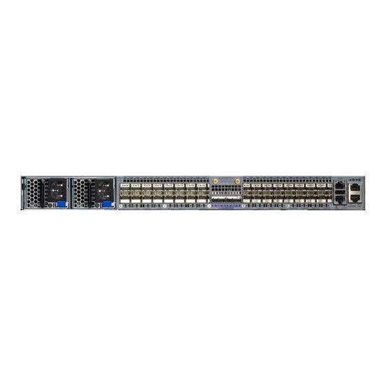
Page 31: Appendix C Front Panel
Appendix C Front Panel This appendix displays the front panel of all switches covered by this guide. Figure C-1: DCS-7020SR-32C2 Quick Start Guide: 7020SR-32C2 Series 1 RU-Gen 3 Data Center Switches... - Page 32 Appendix C: Front Panel Quick Start Guide: 7020SR-32C2 Series 1 RU-Gen 3 Data Center Switches...
-
Page 33: Appendix D Rear Panel
Appendix D Rear Panel All switches covered by this guide use the rear panel shown below. Figure D-1: DCS-7020SR-32C2 Quick Start Guide: 7020SR-32C2 Series 1 RU-Gen 3 Data Center Switches... - Page 34 Appendix D: Rear Panel Quick Start Guide: 7020SR-32C2 Series 1 RU-Gen 3 Data Center Switches...
-
Page 35: Appendix E Maintenance And Field Replacement
• Replacement parts should be the same or compatible with those being replaced. • Before you begin, refer to the Arista Networks document Safety Information and Translated Safety Warnings available at: https://www.arista.com/en/support/product-documentation. Note Refer to the front... -
Page 36: Fan Modules
Step 2 Slide the new fan module into the switch until the module is fully seated and the release lever snaps into place. Step 3 Verify that the fan module is working normally. Note The fan module status LED should be a steady green for normal operation. Quick Start Guide: 7020SR-32C2 Series 1 RU-Gen 3 Data Center Switches... -
Page 37: Appendix F Regulatory Model Numbers
This appendix lists the regulatory model numbers (RMNs), where applicable, for the product models for the switches described in this document. Table F-1 Regulatory Model Numbers and Product Numbers Regulatory Model Number (RMN) Product Number(s) AN1723 DCS-7020SR-32C2 Quick Start Guide: 7020SR-32C2 Series 1 RU-Gen 3 Data Center Switches... - Page 38 Appendix F: Regulatory Model Numbers Quick Start Guide: 7020SR-32C2 Series 1 RU-Gen 3 Data Center Switches...
-
Page 39: Appendix G Taiwan Rohs Information
Appendix G Taiwan RoHS Information This appendix provides Taiwan RoHS information for switches covered by this guide. For Taiwan BSMI RoHS Table, go to https://www.arista.com/assets/data/pdf/AristaBSMIRoHS.pdf. Quick Start Guide: 7020SR-32C2 Series 1 RU-Gen 3 Data Center Switches... - Page 40 Appendix G: Taiwan RoHS Information Quick Start Guide: 7020SR-32C2 Series 1 RU-Gen 3 Data Center Switches...
Need help?
Do you have a question about the 7020SR-32C2 Series and is the answer not in the manual?
Questions and answers