Arista 720XP Series Quick Start Manual
Cognitive campus switches
Hide thumbs
Also See for 720XP Series:
- Quick start manual (38 pages) ,
- Quick start manual (34 pages) ,
- Quick start manual (32 pages)

Related Manuals for Arista 720XP Series


Summary of Contents for Arista 720XP Series
- Page 1 Quick Start Guide 720XP Series 2 RU Cognitive Campus Switches Arista Networks www.arista.com DOC-04208-02...
- Page 2 © Copyright 2022 Arista Networks, Inc. The information contained herein is subject to change without notice. Arista Networks and the Arista logo are trademarks of Arista Networks, Inc in the United States and other countries. Other product or service names may be trademarks or service marks of others.
-
Page 3: Table Of Contents
Contents Contents Chapter 1: Overview................1 1.1 Scope............................1 1.2 Receiving and Inspecting the Equipment................1 1.3 Installation Process.........................1 1.4 Safety Information........................2 1.5 Obtaining Technical Assistance..................... 2 1.6 Specifications.......................... 3 Chapter 2: Preparation................5 2.1 Site Selection..........................5 2.2 Tools and Parts Required for Installation................6 2.3 Electrostatic Discharge (ESD) Precautions................ - Page 4 Appendix F: Taiwan RoHS Information..........29...
-
Page 5: Chapter 1: Overview
• Specifications Scope This guide is intended for properly trained service personnel and technicians who need to install the following Arista Networks Cognitive Campus Switches: CCS-720XP-96ZC2 Important: Only qualified personnel should install, service, or replace this equipment. Seul le personnel qualifié doit installer, service, ou remplacer cet équipement. -
Page 6: Safety Information
Refer to the Arista Networks document Safety Information and Translated Safety Warnings available at:https://www.arista.com/en/support/product-documentation. Obtaining Technical Assistance Any customer, partner, reseller or distributor holding a valid Arista Service Contract can obtain technical support in any of the following ways: •... -
Page 7: Specifications
Overview Specifications The following tables list the specifications of switches covered by this guide Table 1: Switch Specifications (Dimensions and Weights) Switch Size (W x H x D) Weight CCS-720XP-96ZC2 48.3 x 8.8 x 40.4 cm (19 x 3.5 x 15.9 inches) 14.1 kg (31 lbs.) Table 2: Switch Specifications (Operational and Storage) Switch Operating... -
Page 9: Chapter 2: Preparation
Chapter 2 Preparation This chapter includes the following sections: • Site Selection • Tools and Parts Required for Installation • Electrostatic Discharge (ESD) Precautions Site Selection The following criteria should be considered when selecting a site to install the switch: •... -
Page 10: Tools And Parts Required For Installation
Toutes les connexions d'alimentation doivent être enlevées pour hors tension l'appareil. This unit is intended for installation in restricted access areas. Cet appareil est prévu pour une installation dans les zones d'accès restreintes. Tools and Parts Required for Installation The following tools and equipment are required to install the switch: Two-Post Rack •... -
Page 11: Chapter 3: Rack Mounting The Switch
Chapter 3 Rack Mounting the Switch This chapter includes the following sections: • Rack Mounting the Switch • Two-Post Rack Mount Rack Mounting the Switch Important: The rack mounting procedure is identical for all switches covered by this guide. Illustrations in this chapter depict the mounting of a DCS-7050SX-128 switch. -
Page 12: Attaching Mounting Brackets To The Chassis
Figure 1: Bracket Mount Examples for Two-Post Rack Mount Figure 2: Improper Bracket Mount Examples for Two-Post Rack Mount 3.2.1 Attaching Mounting Brackets to the Chassis This procedure attaches mounting brackets to the switch chassis (Figure 3: Attaching the Mounting Brackets to the Switch Chassis). - Page 13 Rack Mounting the Switch 1. Lift the chassis into the rack. Position the flanges against the rack posts. Figure 4: Inserting the Switch into the Rack 2. Select mounting screws that fit your equipment rack. 3. Attach the bracket flanges to the rack posts. After completing the two-post rack mount, proceed to Connecting Power Cables.
-
Page 15: Chapter 4: Cabling The Switch
Chapter 4 Cabling the Switch This chapter includes the following sections: • Connecting Power Cables • Connecting Serial and Management Cables Connecting Power Cables Directions for connecting the power cables. Important: Installation of this equipment must comply with local and national electrical codes. If necessary, consult with the appropriate regulatory agencies and inspection authorities to ensure compliance. -
Page 16: Connecting Serial And Management Cables
For power supply redundancy, at least one more power supply should be installed than is required to power the system. Figure 5: AC Power Supply displays the AC power supply. Figure 5: AC Power Supply 1 PSU handle 2 PSU status LED 3 Release The accessory kit provides IEC-320 C15 to C16 power cables. - Page 17 Cabling the Switch Figure 6: Front Panel Ports 1 Ethernet management port 2 USB port 3 Console serial port Connect the front panel ports as follows: • Console (Serial) Port: Connect to a PC with the RJ-45 to DB-9 serial adapter cable. The switch uses the following default settings: •...
-
Page 19: Chapter 5: Configuring The Switch
Chapter 5 Configuring the Switch Arista switches ship from the factory in Zero Touch Provisioning (ZTP) mode. ZTP configures the switch without user intervention by downloading a startup configuration file or a boot script from a location specified by a DHCP server. To manually configure a switch, ZTP is bypassed. - Page 20 When the management port IP address is configured, use this command to access the switch from a host, using the address configured in step 9: ssh admin@192.0.2.8 Refer to the Arista Networks User Manual for complete switch configuration information.
-
Page 21: Appendix A: Status Indicators
Appendix A Status Indicators This chapter includes the following sections: • Front Indicators • Rear Status Indicators Front Indicators System and port status LED indicators are located on the front of the switches. This section includes the following topics: • Switch Indicators •... -
Page 22: Port Indicators
Table 6: Switch Indicators LED States LED Name LED State Device Status System Status Blinking Green System powering up. Green All power supplies and fans are operating normally. Blue The locator function is active. A power supply or fan is missing or in a failed state. Fan Status Green All fans are operating normally. -
Page 23: Rear Status Indicators
Status Indicators Green Port link is up. Yellow Port is software disabled. Flashing Yellow Port failed diagnostics. Rear Status Indicators Fan and power supply modules are accessed from the rear panel. Each fan and power supply module contains an LED that reports the module status. Rear Panel displays the rear panel of all switches covered by this guide. - Page 24 Note: You can narrow down the error condition by logging in to the switch to view the specific device state. Refer to the Arista User Manual’s Switch Environment Control chapter, under the topic Viewing Environment Status, for further information on the show environment...
-
Page 25: Appendix B: Parts List
List of provided cables. Quantity Description Power cables: IEC-320/C15-C16, 13 A, 250 V, 2 meter RJ-45 Patch Panel Cable, 2 meter RJ-45 to DB9 Adapter Cable, 2 meter Note: All provided power cables are for use only with Arista products. -
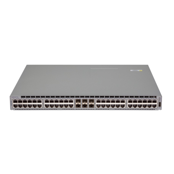
Page 27: Appendix C: Front Panel
Appendix C Front Panel This appendix displays the front panel of all switches covered by this guide. Figure 12: CCS-720XP-96ZC2 1 System status LED 5 USB port 9 5G PoE ports 2 Fan status LED 6 Console serial port 10 2.5G PoE ports 3 PSU status LED 7 25G ports 4 Ethernet management port... -
Page 29: Appendix D: Rear Panel
Appendix D Rear Panel This appendix displays the rear panel of all switches covered by this guide. Depending on the power supply modules installed, the rear panel on your switch may appear slightly different. Figure 13: All Models 1 Fan Module 1 4 Power Supply Module 1 7 Power Supply Module 4 2 Fan Module 2... -
Page 31: Appendix E: Regulatory Model Numbers
Appendix E Regulatory Model Numbers This appendix lists the Regulatory Model Numbers (RMNs) for the product models for the switches described in this document. Table 10: Regulatory Model Numbers and Product Numbers Regulatory Model Number (RMN) Product Name(s) AN1733 CCS-720XP-96ZC... - Page 33 Appendix F Taiwan RoHS Information This appendix provides Taiwan RoHS information for switches covered by this guide. For Taiwan BSMI RoHS Table, go to https://www.arista.com/assets/data/pdf/AristaBSMIRoHS.pdf.
Need help?
Do you have a question about the 720XP Series and is the answer not in the manual?
Questions and answers