
Related Manuals for Arista 7020SR-32C2 Series


Summary of Contents for Arista 7020SR-32C2 Series
- Page 1 Quick Start Guide 7020SR-32C2 Series 1 RU (Gen 3) Data Center Switches Arista Networks www.arista.com DOC-00152-02...
- Page 2 © Copyright 2022 Arista Networks, Inc. The information contained herein is subject to change without notice. Arista Networks and the Arista logo are trademarks of Arista Networks, Inc in the United States and other countries. Other product or service names may be trademarks or service marks of others.
-
Page 3: Table Of Contents
Contents Contents Chapter 1: Overview................1 1.1 Scope............................1 1.2 Receiving and Inspecting the Equipment................1 1.3 Installation Process.........................1 1.4 Safety Information........................2 1.5 Obtaining Technical Assistance....................2 1.6 Specifications.......................... 3 Chapter 2: Preparation................5 2.1 Site Selection..........................5 2.2 Tools and Parts Required for Installation................7 2.3 Electrostatic Discharge (ESD) Precautions................ - Page 4 B.1.2 Two-Post Rack Mount Parts................... 28 B.2 Cables...........................28 Appendix C: Front Panel..............29 Appendix D: Rear Panel............... 31 Appendix E: Maintenance and Field Replacement......33 E.1 Considerations........................33 E.2 Power Supplies........................33 E.2.1 Removing a Power Supply..................33 E.2.2 Installing a Power Supply..................33 E.3 Fan Modules.........................34 E.3.1 Removing a Fan Module..................
-
Page 5: Chapter 1: Overview
Specifications Scope This guide is intended for properly trained service personnel and technicians who need to install the following Arista Networks Data Center Switches: DCS-7020SR-32C2 Important: Only qualified personnel should install, service, or replace this equipment. Seul le personnel qualifié doit installer, service, ou remplacer cet équipement. -
Page 6: Safety Information
L'élimination finale de ce produit doit être effectuée conformément à toutes les lois nationales etrèglements. Safety Information Refer to the Arista Networks document Safety Information and Translated Safety Warnings available at https://www.arista.com/en/support/product-documentation. Obtaining Technical Assistance Any customer, partner, reseller or distributor holding a valid Arista Service Contract can obtain technical support in any of the following ways: •... -
Page 7: Specifications
VDC / 9 A Note: All PSU models are not supported by all switches. Some switches described in this guide could use power supplies that may no longer be available. Contact your local Arista representative for more information. Table 5: Switch Specifications (Power Draw) -
Page 9: Chapter 2: Preparation
Chapter 2 Preparation The following topics are covered in this section: • Site Selection • Tools and Parts Required for Installation • Electrostatic Discharge (ESD) Precautions Site Selection The following criteria should be considered when selecting a site to install the switch: •... - Page 10 Two circuits provide redundancy protection. Cabling the Switch describes power cable requirements. Figure 1: Airflow Direction 1 Ground Lug 6 ESD 2 Blue Handles indicates forward airflow 7 Console (Serial) Port 3 Ethernet Management Port 8 USB Port 4 System Status LED 9 Power Supply 2 Status LED 5 Fan Status LED 10 Power Supply 1 Status LED...
-
Page 11: Tools And Parts Required For Installation
Preparation Tools and Parts Required for Installation Each switch provides an accessory kit that contains parts that are required to install the switch. In addition to the accessory kit, the following tools and equipment are required to install the switch: Two-Post Rack •... -
Page 13: Chapter 3: Rack Mounting The Switch
Chapter 3 Rack Mounting the Switch Important: The rack mounting procedure is identical for all switches covered by this guide. Illustrations in this chapter depict the mounting of a DCS-7020SR-32C2 switch. Les procédure de montage du bâti est identique pour tous les commutateurs visés par ce guide. -
Page 14: Inserting The Switch Into The Rack
3.1.2 Inserting the Switch into the Rack This procedure attaches the switch to the rack (Figure 3-2). 1. Lift the chassis into the rack. Position the mounting ears against the rack posts. Note: The mounting ears should be at the same height to ensure that the device is level. 2. -
Page 15: Assembling The Rails Onto The Equipment Rack
Rack Mounting the Switch 2. Use the screws to attach the brackets to the chassis. Figure 4: Attaching Mounting Brackets to the Switch Chassis 3.2.2 Assembling the Rails onto the Equipment Rack Rail-rods and rail-slides assemble into two identical rails. Each rail connects a front post to a rear post. When the rails are installed, the switch slides on the rails into the rack. - Page 16 Note: The rail clip prevents the extension of the rail beyond the maximum supported distance between the front and rear rack posts. Figure 6: Assembling the Rails 1 Rail Slide 3 Rail (assembled) 2 Rail Rod A Rack Plugs 2. Attach rail to the right rear rack post by inserting rod-end rack plugs into post slots (Figure 7: Attaching the Rails ).
-
Page 17: Attaching The Switch To The Rack
Rack Mounting the Switch 3.2.3 Attaching the Switch to the Rack After the rails are installed, the switch slides on the rails into the rack. Each bracket includes a thumb screw that attaches the switch to the rail. 1. Lift the switch into the rack and insert the mounting brackets into the slide rails (Figure 8: Inserting the Switch onto the Rails). -
Page 19: Chapter 4: Cabling The Switch
Chapter 4 Cabling the Switch The following topics are covered in this section: • Grounding the Switch • Connecting Power Cables • Connecting Serial and Management Cables Grounding the Switch After mounting the switch into the rack, connect the switch to the data center ground. Figure 4-1 displays the location of the grounding lug on the front, left mounting ear for the DCS-7020SR-32C2 Important: Grounding wires and grounding lugs (M4 x 0.7) are not supplied. -
Page 20: Ac Power Supplies
Installation de cet équipement doit être conformes aux codes électriques locaux et nationaux. Si nécessaire, consulter les organismes de réglementation appropriés et des autorités de contrôle pour assurer la conformité. The switch operates with two installed power supplies. At least one power supply must connect to a power source. -
Page 21: Dc Power Supplies
Cabling the Switch 4.2.2 DC Power Supplies The PWR-400-DC power supply is supported. The following figure displays a PWR-400-DC power supply. It connects to a circuit that provides the required power, as specified by Table 5: Switch Specifications (Power Draw). Figure 12: DC Power Supply (PWR-400-DC) 1 Status LED 3 PSU Handle... - Page 22 1. Attach an ESD grounding strap. 2. Prepare the stranded copper wiring for the power supply to be used. Table 6: Wiring, Lug, and Tightening Torques for DC PSUs provides wiring, lug, and tightening torque information for the power supplies covered in this guide. Table 6: Wiring, Lug, and Tightening Torques for DC PSUs Wire Size Lug Type...
-
Page 23: Connecting Serial And Management Cables
Cabling the Switch Assurez-vous de pouvoir retirer des circuits en courant continu avant d’effectuer toute action d’installation.Localiser les disjoncteurs ou fusibles sur les lignes électriques DC entretien des circuits. Mettez hors tension le circuit ligne ou retirer les fusibles. Important: Wire size must comply with local and national requirements and electrical codes. - Page 24 Figure 14: Management Ports display the management, console, and USB ports on the front panel. Figure 14: Management Ports 1 Link status LED 4 USB port 2 Activity status LED 5 Serial (console) port 3 Ethernet Management port Connect the ports as follows: •...
-
Page 25: Chapter 5: Configuring The Switch
Chapter 5 Configuring the Switch Arista switches ship from the factory in Zero Touch Provisioning (ZTP) mode. ZTP configures the switch without user intervention by downloading a startup configuration file or a boot script from a location specified by a DHCP server. To manually configure a switch, ZTP is bypassed. The initial configuration provides one username (admin) accessible only through the console port because it has no password. - Page 26 When the management port IP address is configured, use this command to access the switch from a host, using the address configured in Step 9. ssh admin@192.0.2.8 Refer to the Arista Networks User Manual for complete switch configuration information.
-
Page 27: Appendix A: Status Indicator Leds
Appendix A Status Indicator LEDs The following topics are covered in this section: • System-Level Status Indicator LEDs • Component Status Indicators System-Level Status Indicator LEDs Status indicator LEDs are located on the chassis and on some of the components like PSUs and Fan modules. -
Page 28: Fan Status Indicator Led
Note: Arista fixed-form switches take approximately 5 to 10 minutes to boot completely. A.1.2 Fan Status Indicator LED Figure 15: System Status and Fan Status Indicators display the fan status LED for the system. Table 9: Fan Status Indicator LED States... -
Page 29: Component Status Indicators
Status Indicator LEDs Component Status Indicators The following topics are covered in this section: • Fan Module Status LED • PSU Module Status LED A.2.1 Fan Module Status LED Each fan and power supply module has an LED that reports the module status. Fan module status LED is on the fan module (Figure 17: Fan Module Status LED ) and is different from the system-level fan... -
Page 30: Psu Module Status Led
Note: You can narrow down the error condition by logging in to the switch to view the specific device state. Refer to the Arista User Manual’s Switch Environment Control chapter, under the topic Viewing Environment Status, for further information on the show environment... -
Page 31: Appendix B: Parts List
Appendix B Parts List Each switch provides an accessory kit that contains parts that are required to install the switch. This appendix lists the installation parts contained in the switch accessory kit. Note: The accessory kit is included in a bag. For DCS-7020SR-32C2, four-post rack kit is optional and sold separately. -
Page 32: Two-Post Rack Mount Parts
Figure 20: Two-Post Rack Mount Parts for DCS-7020SR-32C2 Cables Quantity Description Power cables: IEC-320/C13- C14, 13 A, 250 V RJ-45 Patch Panel Cable RJ-45 to DB9 Adapter Cable Warning: All provided power cables are for use only with Arista products. -
Page 33: Appendix C: Front Panel
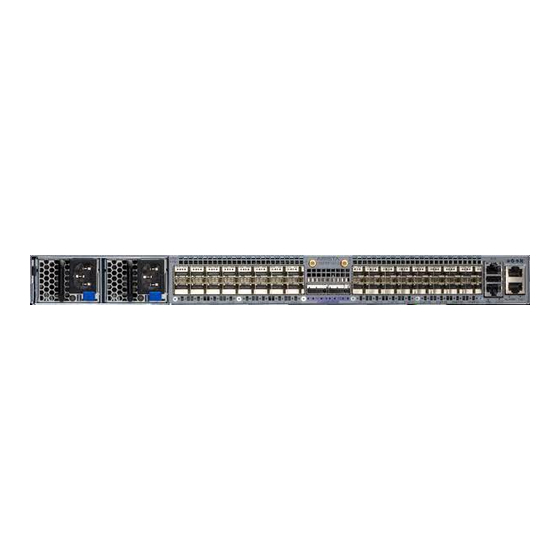
Appendix C Front Panel This appendix displays the front panel of all switches covered by this guide. Note: Depending on the power supplies installed, your switch may look different. Figure 21: DCS-7020SR-32C2 1 Ground lug 6 ESD 2 Blue handle indicates forward airflow 7 Console (serial) port 3 Ethernet management port 8 USB port... -
Page 35: Appendix D: Rear Panel
Appendix D Rear Panel All switches covered by this guide use the rear panel shown below. Figure 22: DCS-7020SR-32C2 1 Fan module 1 handle 3 Ground 5 Fan module 1 status LED 2 Fan module 3 handle 4 Fan module 3 status LED... -
Page 37: Appendix E: Maintenance And Field Replacement
• Replacement parts should be the same or compatible with those being replaced. • Before you begin, refer to the Arista Networks document Safety Information and Translated Safety Warnings available at: https://www.arista.com/en/support/product-documentation. Note: Refer to the front (Front... -
Page 38: Fan Modules
Note: The Power Supply status LED should be a steady green for normal operation. 6. Verify the new power supply operation by issuing the show environment power command. switch#show environment power Note: The output of the command lists the power supplies in operation and should include the one you replaced. -
Page 39: Appendix F: Regulatory Model Numbers
Appendix F Regulatory Model Numbers This appendix lists the Regulatory Model Numbers (RMNs), where applicable, for the product models for the switches described in this document. Table 13: Regulatory Model Numbers and Product Numbers Regulatory Model Number (RMN) Product Number(s) AN1723 DCS-7020SR-32C2... -
Page 41: Appendix G: Taiwan Rohs Information
Appendix G Taiwan RoHS Information This appendix provides Taiwan RoHS information for switches covered by this guide. For Taiwan BSMI RoHS Table, go to https://www.arista.com/assets/data/pdf/AristaBSMIRoHS.pdf.
Need help?
Do you have a question about the 7020SR-32C2 Series and is the answer not in the manual?
Questions and answers