Sullair 300HH Operators Manual And Parts Lists
Portable
Hide thumbs
Also See for 300HH:
- Operator's manual and parts list (120 pages) ,
- User manual (80 pages) ,
- User manual (74 pages)
Table of Contents
Advertisement
Quick Links
Download this manual
See also:
User Manual
P
ortable
300HH, 375, 375H, 375HH, 425
John Deere Standard and Aftercooled and Filtered
a
C
ir
omPressor
425H
and
Part Number:
02250169-727 r02
©
keeP for
future
refereNce
Sullair corPoratioN
The information in this document
is correct at the time of printing for
portable compressor serial number
200803170000
and all subsequent serial numbers.
Advertisement
Table of Contents

Related Manuals for Sullair 300HH


Summary of Contents for Sullair 300HH
- Page 1 300HH, 375, 375H, 375HH, 425 425H John Deere Standard and Aftercooled and Filtered Part Number: 02250169-727 r02 keeP for future refereNce Sullair corPoratioN © The information in this document is correct at the time of printing for portable compressor serial number 200803170000 and all subsequent serial numbers.
- Page 2 Sullair equipment. Individual seminars on Portable compressors are presented at regular intervals throughout the year at a dedicated training facility at Sullair’s corporate headquarters in Michigan City, Indiana. Instruction includes discussion of the function and installation of Sullair service parts, troubleshooting of the most common problems, and actual equipment operation.
-
Page 3: Table Of Contents
DeScriPtioN ....................13 Introduction ....................13 Description Of Components ................13 Sullair Compressor Unit, Functional Description .......... 15 Compressor Cooling And Lubrication System, Functional Description ..15 Compressor Discharge System, Functional Description ....... 16 Capacity ContRol SysTem, Functional Description ........16 Start –... - Page 4 Air Inlet System & Exhaust System .............. 88 Control Parts & Discharge Parts - 375 and 425 ..........92 Control Parts & Discharge Parts - 300HH, 375H, 375HH and 425H ..100 Regulator/Blowdown Valve - 375 And 425 ..........108 Regulator/Blowdown Valve - 300HH, 375H, 375HH and 425H ....
- Page 5 Control Parts Orifice - 300HH, 375H, 375HH and 425H ......112 Service Valves..................... 114 Optional AfterCooler/Filter And Parts ............116 Electrical Parts .................... 124 Instrument Panel & Parts ................128 Fuel Tank & Connections ................132 Frame, Axle & Parts And Axle Assembly ............. 134 Axle Assembly—American models .............
- Page 6 table of coNteNtS tHiS PaGe iNteNtioNallY left blaNk 375 John Deere Standard and Aftercooled/Filtered Operator’s Manual and Parts List...
-
Page 7: Safety
GeNeral 8-hour work week is 3 years. these conditions exist on an 8-hour shift Sullair Corporation designs and manufactures all of its only. any other operation of the products so they can be operated safely. However, the equipment other than 8-hour shifts... - Page 8 SectioN 1 Prior to hitching the air compressor to the tow vehicle, If provided, make sure chain length, brake and inspect all attachment parts and equipment, checking electrical interconnections provide sufficient slack to for (i) signs of excessive wear or corrosion, (ii) parts prevent strain when cornering and maneuvering, yet that are cracked, bent, dented or otherwise deformed are supported so they cannot drag or rub on road,...
-
Page 9: Towing
SafetY If provided, make sure all dual stop, tail directional Maneuver in a manner that will not exceed the and clearance lights are operating properly and that freedom of motion of the compressor’s drawbar and/ their lenses are clean and functional. Also, make sure or coupling device, in or on the towing vehicle’s all reflectors and reflecting surfaces, including the coupling device and/or adjacent structure whether... -
Page 10: Pressure Release
SectioN 1 Lower front screw jack and/or any front and rear When possible, stow hinged drawbar in the vertical stabilizer legs. Make sure the surface they contact upright position. Make certain it is securely latched in has sufficient load bearing capability to support the the vertical upright position. -
Page 11: Fire And Explosion
SafetY Vent all internal pressure prior to opening any line, Clean up spills of fuel, fluid, battery electrolyte or fitting, hose, valve, drain plug, connection or other coolant immediately if such spills occur. component, such as filters and line oilers, and before Shut off air compressor and allow it to cool. -
Page 12: Moving Parts
SectioN 1 Keep oily rags, trash, leaves, litter or other Turn the battery disconnect switch to the off position combustibles out of and away from the compressor. to prevent accidental engine operation prior to attempting repairs or adjustments. Tag the battery Open all access doors and allow the enclosure to connection so others will not unexpectedly reconnect ventilate thoroughly prior to attempting to start the... -
Page 13: Electrical Shock
SafetY Do Not use air line anti-icer systems in air lines Keep all parts of the body and any hand-held tools or supplying respirators or other breathing air utilization other conductive objects away from exposed live equipment and Do Not discharge air from these parts of electrical system. -
Page 14: Entrapment
SectioN 1 eNtraPmeNt Avoid accidental contact between jumper cable 1.10 terminal clips or clamps and any metallic portion of either the compressor or the starting vehicle to Make sure all personnel are out of compressor before minimize the possibility of uncontrolled arcing which closing and latching enclosure doors. -
Page 15: Implementation Of Lockout/Tagout
SafetY Remove and carefully dispose of the dampened of person affixing tag to power source must be on cloths, as they may now be contaminated with acid, tag along with date tag was placed on power then replace all vent caps. source. -
Page 16: Symbols And References
SectioN 1 SYmbolS aND refereNceS 1.14 The symbols below may or may not be used. Please refer to the decals set forth on the machine for applicable symbols. Safety Symbols-1... - Page 17 SafetY Safety Symbols-2...
- Page 18 SectioN 1 Safety Symbols-3...
-
Page 19: Description
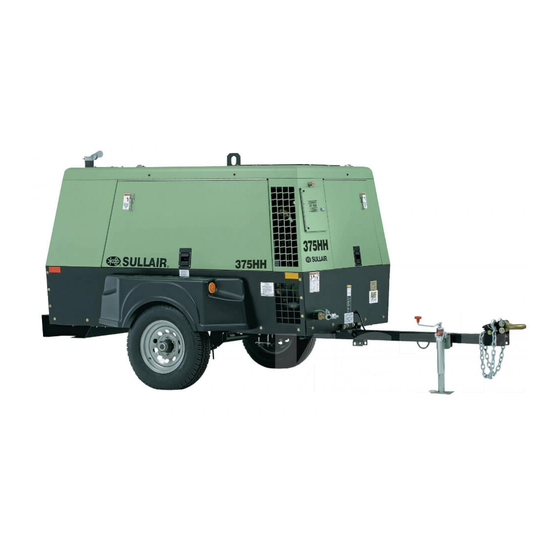
The Sullair 300HH, 375, 375H, 375HH, 425, and 425H and electrical system. A low profile canopy offers CFM Standard and Aftercooled Portable Air Compressors improved handling and mobility. - Page 20 Battery Shutoff Switch Optional Discharge Air Filters Figure 2-1: Sullair Rotary Screw Portable Air Compressor – John Deere Standard and Aftercooled Models Refer to the engine operator’s manual for a more The control system can easily be adjusted for pressures from 80 to 125 psig (5.6 to 8.6 bar) for standard machines,...
-
Page 21: Sullair Compressor Unit, Functional Description
When the temperature reaches 155°F (68°C), the provide continuous (pulse-free) compression to meet thermostat is fully open allowing all fluid entering the various demand loads. Sullair compressors require no thermal valve to flow to the cooler. routine maintenance or inspection of their internal parts or The cooler is a radiator type that works in concert with the systems. -
Page 22: Compressor Discharge System, Functional Description
SYStem, DeScriPtioN fuNctioNal DeScriPtioN Refer to Figure 2-3. The Sullair compressor unit Refer to Figure 2-4, Figure 2-5, Figure 2-6 or Figure 2-7. discharges a compressed air/fluid mixture into the receiver The purpose of the control system is to regulate the tank. - Page 23 DeScriPtioN STANDARD MODEL AFTERCOOLED MODEL SU_0000665 Engine Receiver Tank (Sump) Strainer Optional Discharge Air Filters Minimum Pressure/Check Valve Moisture Separator Service Air Outlet Aftercooler Receiver Tank (Sump) Separator Element Fluid/Air Non-Aftercooled/Aftercooled Service Air Valve Service Air Outlet Figure 2-3: Compressor Discharge System – Standard and Aftercooled Models 375 John Deere Standard and Aftercooled/Filtered Operator’s Manual and Parts List...
- Page 24 SectioN 2 SU_0000666 Air Pressure Gauge Optional Aftercooler Instrument Panel Aftercooled Machines ONLY Idle Warm-Up Valve Fluid Filter Inlet Valve Thermal Valve Air Filter Compressor Unit Regulator/Blowdown Valve Manifold Fluid Cooler Minimum Pressure/Check Valve Pressure Relief Valve Fluid/Air Fuid Fill/Fluid Level Sight Glass Fluid Optional Discharge Air Filters Strainer...
- Page 25 Silencer Fluid Cooler Inlet Valve Strainer Fluid/Air Minimum Pressure/Check Valve Fluid Pressure Relief Valve Figure 2-5: Control System with Piping and Instrumentation – 300HH, 375H, 375HH and 425H Models 375 John Deere Standard and Aftercooled/Filtered Operator’s Manual and Parts List...
- Page 26 SectioN 2 02250169-746R01 Figure 2-6: Piping and Instrumentation Diagram 375 John Deere Standard and Aftercooled/Filtered Operator’s Manual and Parts List...
- Page 27 DeScriPtioN Filter, Air Compressor Discharge Temperature Switch Gauge, Filter Restriction (Optional) Inlet Valve Compressor Gauge, Temperature Switch, Temperature Valve, Relief Receiver, Air/Oil Glass, Sight Oil Level Indicator, Delta-P Valve, Minimum Pressure/Check Valve, Ball Cooler, Air Separator, Moisture Trap, Drain Orifice Valve, Blowdown N.C.
- Page 28 SectioN 2 Air Intake and Exhaust System Compressor Intake Manifold Turbine Fuel System Injector Relief Valve (Filter Head) Customer Supplied Ether Bottle John Deere Only Internal Relief Valve Cooling System Heads and Cylinder Lubrication System Engine Lube System/ Block and Turbo 02250169-746R00-2 Figure 2-7: Piping and Instrumentation Diagram 375 John Deere Standard and Aftercooled/Filtered Operator’s Manual and Parts List...
- Page 29 DeScriPtioN Turbocharger, Compressor Coolant Level Cooler, Air Fuel Level Muffler, Engine Oil Level (Dipstick) Fuel Level Sender Inlet Manifold Air Pressure Rain Cap, Exhaust System Fuel Pressure Fuel Filter W/ Water Separator Oil Pressure Fuel Transfer Pump (Internal To Engine) Fuel Temperature Hand Operated Fuel Priming Pump Coolant Temperature...
-
Page 30: Normal Operation - 80 To 100 Psig (5.6 To 6.9 Bar) Or 80 To 150 Psig (5.6 To 10.3 Bar) For H Machines Or 80 To 200 Psig (5.6 To 13.8 Bar) For Hh Machines
SectioN 2 pressure increases, the inlet valve piston will further close the inlet valve and the engine speed will decrease until it reaches its preset idle speed. When the demand on the compressor increases, the sump pressure falls below 110 psig (7.6 bar) or 165 psig (11.4 bar) for “H”... - Page 31 DeScriPtioN SU_0000674 Compressor Discharge Temperature Gauge Engine Warning Lamp System Air Pressure Gauge Engine Wait to Start Lamp Start/Stop Switch Engine Stop Lamp Warm-up Control Switch Fuel Level (optional) High/Low Pressure Selector Switch Engine PowerView Monitor Shutdown Indicator Figure 2-9: Instrument Panel Group Refer to Figure 2-9 for the locations of the following The shutdown indicator light indicates engine and indicators and controls:...
- Page 32 SectioN 2 Using the Diagnostic Gauge to Access Engine Information Refer to Figure 2-10. The diagnostic gauge (Figure 2-10, [1]) displays engine function and trouble codes (DTCs). The display can be set for either English or metric units. It is linked to the electronic control system sensors and allows the operator to monitor engine functions and troubleshoot malfunctions.
- Page 33 DeScriPtioN Main Menu Navigation Note if the engine is not running, the diagnostic screens can be viewed but they will not show any operating or performance data. once the engine is started, the screens will display the engine’s operating information. Turn the switch to the ON position.
- Page 34 SectioN 2 Pressing the right arrow key will scroll down to reveal the last items of the Main Menu screen, highlighting ADJUST CONTRAST the next item down. UTILITIES Last Items On Main Menu SU_0000495 Figure 2-14 Use the arrow keys to scroll to the desired menu item or press the Menu Button to exit the Main Menu and GOTO 1-UP DISPLAY 1000 RPM...
- Page 35 DeScriPtioN The Main Menu will be displayed. Use the arrow keys to scroll through the menu until ENGINE CONFIG is GOTO 1-UP DISPLAY STORED CODES highlighted. ENGINE CONFIG SETUP 1-UP DISPLAY SETUP 4-UP DISPLAY SELECTED UNITS ADJUST BACKLIGHT SELECT ENGINE CONFIGURATION SU_0000498 Figure 2-17 Once the ENGINE CONFIG menu item has been...
- Page 36 SectioN 2 Press the Menu key to exit the Main Menu and return to the engine parameter display. 1000 RPM LOAD@RPM ENG RPM 1800 RPM 14.2 57 PSI BAT VOLT OIL PRES COOL TEMP ENG RPM Exit Main Menu SU_0000502 Figure 2-21 Accessing Stored Trouble Codes Note...
- Page 37 DeScriPtioN Once the STORED CODES menu item has been highlighted, press the ENTER key to view the stored GOTO 1-UP DISPLAY STORED CODES codes. ENGINE CONFIG SETUP 1-UP DISPLAY SETUP 4-UP DISPLAY SELECTED UNITS ADJUST BACKLIGHT Enter Key SU_0000505 Figure 2-24 If the word NEXT appears above the arrow keys, there are more stored codes that can be viewed.
- Page 38 SectioN 2 Accessing Active Trouble Codes Note the engine does not need to be running to navigate the diagnostic gauge screens. if engine start up is desired, See Starting the engine. all of the engine values shown on the diagnostic gauge indicate the engine is running.
- Page 39 DeScriPtioN To acknowledge and hide the code and return to the WARNING single or four parameter display, press the ENTER 1 of x SPN 94 FMI 18 key. FAULT: FUEL DELIVERY PRESSURE CORRECTIVE ACTION: imPortaNt: ignoring active trouble codes can CHECK FUEL FILTER AND LINES <...
-
Page 40: Normal Operation
SectioN 2 Engine Shutdown Codes During normal operation the single or four parameter screen will be displayed. 1000 RPM LOAD@RPM ENG RPM 1800 RPM 14.2 57 PSI BAT VOLT OIL PRES COOL TEMP ENG RPM Normal Operation SU_0000514 Figure 2-35 When the diagnostic gauge receives a severe trouble code from the engine control unit, the single of four SHUTDOWN... - Page 41 DeScriPtioN Pressing the ENTER key once again will hide the trouble code and return the screen to the single or SHUTDOWN 1 of x SPN 100 FMI 1 four parameter display. FAULT: FUEL DELIVERY PRESSURE CORRECTIVE ACTION: CHECK FUEL FILTER AND LINES <...
- Page 42 SectioN 2 Once the ADJUST BACKLIGHT menu item has been highlighted, press the ENTER key to activate the GOTO 1-UP DISPLAY ADJUST BACKLIGHT function. STORED CODES ENGINE CONFIG SETUP 1-UP DISPLAY SETUP 4-UP DISPLAY SELECTED UNITS ADJUST BACKLIGHT Press Enter Key SU_0000522 Figure 2-43 Use the arrow keys to select the desired backlight...
- Page 43 DeScriPtioN Adjusting Contrast Turn the switch to the ON position. Starting at the single or four engine parameter display, press the 1000 RPM LOAD@RPM Menu key. ENG RPM 1800 RPM 14.2 57 PSI BAT VOLT OIL PRES ENG RPM COOL TEMP Menu Key SU_0000525 Figure 2-47...
- Page 44 SectioN 2 Press the Menu key to return to the Main Menu. ADJUST CONTRAST < > Return To Main Menu SU_0000529 Figure 2-51 Press the Menu key to exit the Main Menu and return to the engine parameter display. 1000 RPM LOAD@RPM ENG RPM 1800 RPM...
- Page 45 DeScriPtioN Once the SELECT UNITS menu item has been highlighted, press the ENTER key to access the GOTO 1-UP DISPLAY STORED CODES ADJUST CONTRAST function. ENGINE CONFIG SETUP 1-UP DISPLAY SETUP 4-UP DISPLAY SELECTED UNITS ADJUST BACKLIGHT Press Enter Key SU_0000533 Figure 2-55 There are three choices for units of measurement:...
- Page 46 SectioN 2 Press the Menu key to return to the engine parameter display. 1000 RPM LOAD@RPM ENG RPM 1800 RPM 14.2 57 PSI BAT VOLT OIL PRES ENG RPM COOL TEMP Press Menu Key SU_0000537 Figure 2-59 Setup 1-Up Display Turn the switch to the ON position.
- Page 47 DeScriPtioN Three options are available for modification of Setup 1-Up Display. USE DEFAULTS CUSTOM SETUP Use Defaults – This option contains the following AUTOMATIC SCAN OFF engine parameters for display: Engine Hours, Engine Speed, Battery Voltage, % Load, Coolant Temperature, and Oil Pressure. Custom Setup –...
- Page 48 SectioN 2 Custom Setup – To perform a custom setup of the SETUP 1-UP DISPLAY, use the arrow buttons to USE DEFAULTS scroll and highlight CUSTOM SETUP on the display. CUSTOM SETUP AUTOMATIC SCAN OFF Selected Custom Setup SU_0000545 Figure 2-67 Press the ENTER key to display a list of engine parameters.
- Page 49 DeScriPtioN Use the arrow keys to scroll and highlight the desired parameter that has not been selected for display ENGINE SPEED (parameter with a number to the right of it). PERCENT LOAD AT CURRENT RPM 2 ENGINE OIL PRESSURE ENGINE COOLANT TEMPERATURE Note that the numbers now indicate the new order of display for the...
- Page 50 SectioN 2 Press the ENTER key again to toggle the AUTOMATIC SCAN function off. Automatic Scan Off SU_0000688 Figure 2-75 Once the USE DEFAULTS, CUSTOM SETUP and AUTOMATIC SCAN functions have been set, press USE DEFAULTS CUSTOM SETUP the Menu key to return to the Main Menu. AUTOMATIC SCAN ON Menu Key SU_0000553...
- Page 51 DeScriPtioN The Main Menu will be displayed. Use the arrow keys to scroll through the menu until SETUP 4-UP GO TO 1-UP DISPLAY DISPLAY is highlighted. STORED CODES ENGINE CONFIG SETUP 1-UP DISPLAY SETUP 4-UP DISLAY SELECTED UNITS ADJUST BACKLIGHT MENU DISPLAY SU_0000556 Figure 2-79...
- Page 52 SectioN 2 Custom Setup – To perform a custom setup of the SETUP 4-UP DISPLAY, use the arrow buttons to USE DEFAULTS CUSTOM SETUP scroll and highlight CUSTOM SETUP on the display. Custom Setup SU_0000560 Figure 2-83 The quadrant with the highlighted parameter value is the current selected parameter.
- Page 53 DeScriPtioN Press the ENTER key to change the selected parameter in the quadrant to the new parameter. ENGINE SPEED ENGINE HOURS ENGINE COOLANT TEMPERATURE 1 BATTERY POTENTIAL ENGINE OIL TEMPERATURE ENGINE OIL PRESSURE Enter Selected Parameter SU_0000564 Figure 2-87 Use the Menu key to return to the SETUP 4-UP DISPLAY screen.
- Page 54 SectioN 2 Press the Menu key to exit the Main Menu and return to the engine parameter display. GO TO 1-UP DISPLAY 125% 1000 RPM STORED CODES LOAD@RPM ENG RPM ENGINE CONFIG SETUP 1-UP DISPLAY SETUP 4-UP DISPLAY 143°F 57 PSI SELECTED UNITS OIL TEMP OIL PRES...
-
Page 55: Wiring Diagram
DeScriPtioN wiriNG DiaGram 375 John Deere Standard and Aftercooled/Filtered Operator’s Manual and Parts List... -
Page 56: Electrical System, Functional Description
SectioN 2 electrical SYStem, comPreSSor SHutDowN 2.10 2.11 fuNctioNal DeScriPtioN & warNiNG SYStem, fuNctioNal DeScriPtioN The electrical system consists of the basic electrical elements required to operate the compressor and also has The Shutdown System and Annunciator Module (SSAM) a system feature that automatically shuts down the continuously monitors the status of the compressor. -
Page 57: Aftercooled And Filtered Air System, Functional Description
DeScriPtioN aftercooleD aND filtereD from the first stage filter. the condensate should be 2.12 drained and stored in a suitable container. From the air SYStem, fuNctioNal first stage filter, the air enters the (optional) second stage DeScriPtioN filter. This filter removes smaller particles and any additional water. -
Page 58: Listing Of Engine Diagnostic Codes (Dtcs)
SectioN 2 liStiNG of eNGiNe 2.13 DiaGNoStic coDeS (DtcS) Note Not all of these codes are used on all oem engine applications. third column below is for blink code retrieval method only. Trouble Codes Dtcs listing in ascending SPN/fmi codes fmi blink Description of fault corrective action... - Page 59 DeScriPtioN Dtcs listing in ascending SPN/fmi codes fmi blink Description of fault corrective action code 000111 Engine Coolant Level Low Check Operator’s Manual “Adding Coolant” 000158 ECU Power Down Error (internal ECU problem) Contact Servicing Dealer 000160 — Axle Speed Unreliable Contact Servicing Dealer 000174 —...
- Page 60 SectioN 2 Dtcs listing in ascending SPN/fmi codes fmi blink Description of fault corrective action code 000654 Injector Number 4 Circuit Has High Resistance Check Injector Wiring or Injector Solenoid Injector Number 4 Circuit Has Low Resistance Check Injector Wiring or Injector Solenoid Injector Number 4 Not Responding Injector Failed or Flow Limiter Closed...
- Page 61 DeScriPtioN Dtcs listing in ascending SPN/fmi codes fmi blink Description of fault corrective action code When reading blink codes, signifies start of active codes When reading blink codes, signifies start of stored codes When reading blink codes, signifies that no fault codes are in the buffer 375 John Deere Standard and Aftercooled/Filtered Operator’s Manual and Parts List...
- Page 62 SectioN 2 tHiS PaGe iNteNtioNallY left blaNk 375 John Deere Standard and Aftercooled/Filtered Operator’s Manual and Parts List...
-
Page 63: Specifications
Section 3 SPecificatioNS SPecificatioNS – 300HH, 375, 375H JoHN Deere DimeNSioNS model Series length (i) width Height weight (wet) 300HH, 375, 375H 156.2 3967.5 77.2 1960.9 74.0 1879.6 4440* 2014.0* 2-Wheel (III) 300HH, 375, 375H 98.8 2509.5 59.3 1506.2 63.6 1615.4... -
Page 64: Specifications - 375Hh, 425 And 425H John Deere
SectioN 3 comPreSSor 300HH 375H Axle Rating (III) 5000 lbs 5000 lbs 5000 lbs (2268 kg) (2268 kg) (2268 kg) Sound Level (US EPA) 76 dBA 76 dBA 76 dBA Sound Level (CE) 71 dBA 71 dBA 71 dBA Sound level measured per U.S. CFR Ch. 1 Part 204... - Page 65 SPecificatioNS comPreSSor 375HH 425H Sump Capacity 7 US gallons 7 US gallons 7 US gallons (26.5 liters) (26.5 liters) (26.5 liters) Track Width (III) 67.5" 67.5" 67.5" (1714.5 mm) (1714.5 mm) (1714.5 mm) Tire Size (Load Range) (III) H78 x 15ST (D) H78 x 15ST (D) H78 x 15ST (D) Tire Pressure (III)
-
Page 66: Lubrication Guide - Compressor
0 to 100 (-18 to 38) MIL-L-2104E 10W 0 to 100 (-18 to 38) (i) Sullair part numbers for Sullair AWF are 250030-757 (5 gallons/18.9 liters) and 250030-758 (55 gallon drum/208 liters). aPPlicatioN GuiDe Sullair air compressors are supplied with Sullair AWF... -
Page 67: General
Fluid Sight Level Glass Indicates the fluid level in the sump. Proper level is marked While Sullair has built into this compressor a complete set halfway up the sight glass. Check the level when the of controls and indicators that allow the operator to control compressor is shutdown and on level ground. -
Page 68: Initial Startup/Shutdown Procedure
SectioN 4 Shutdown System/Annunciator Module (SSAM) Shutdown Monitors the compressor safety system for conditions Close the service valves and run the compressor for requiring shutdown. The annunciator on the instrument approximately five minutes to allow the compressor to control will flash the applicable shutdown code. cool down. -
Page 69: Maintenance
Section 5 maiNteNaNce warNiNG cautioN Do Not remove caps. Plugs the radiator and engine cooling and/or other components when system must be drained and flushed the compressor is running or periodically. refer to the oem engine pressurized. Shutdown the manual for more information. replace compressor before removing any the coolant with a solution of 50% components. -
Page 70: Maintenance After Initial 50 Hours Of Operation
SectioN 5 maiNteNaNce after iNitial 50 Change the compressor fluid if it is not Sullair AWF: HourS of oPeratioN Run the compressor for five to ten minutes to warm the fluid. After the initial 50 hours of operation, the following... -
Page 71: Part Replacement And Adjustment Procedures
maiNteNaNce Part rePlacemeNt aND Refer to Figure 5-2. Air filter maintenance should be performed as often as conditions require. If the filters are aDJuStmeNt ProceDureS equipped with optional maintenance indicators, change the filters every time the indicators show a change is Compressor Fluid Change Procedure necessary. -
Page 72: Element Inspection
Refer to Figure 5-4 and Figure 5-5. Before adjusting the compressor’s control system, the rated full-load pressure and the high/low rpm settings must be determined. This information is provided in Specifications on page 57 and on page 58 or can be obtained by contacting a Sullair representative. SU_0000670 Capscrew... - Page 73 maiNteNaNce Adjust the pressure regulator setting to maintain 115 psig (8 bar) receiver tank pressure. Gradually open the service valve to atmosphere until the engine speed increases and the receiver tank pressure stabilizes at 100 psig (6.9 bar). Adjust the engine high idle speed to its specified setting with the HI (+) or HI (-) buttons on the speed control module.
-
Page 74: Bearing Lubrication (American Models)
SectioN 5 The following steps apply to “H” and “HH” compressors Bearing Lubrication (American Models) equipped with dual pressure controls. Refer to Figure 5-6. Proper lubrication of the portable Start the compressor and allow the engine to warm up compressor’s bearing axle is critical to its proper function to its normal operating temperature with the service and reduction of wear on this part. -
Page 75: First And Second Stage Discharge Air Filter Maintenance - Aftercooled & Filtered Models
maiNteNaNce First and Second Stage Discharge Air Filter Maintenance – Aftercooled & Filtered Models General Refer to Figure 5-7. Familiarity with the filtration process and the unit’s monitoring system (consisting of a compete set of gauges) will enable the operator to locate and analyze malfunctions. -
Page 76: Trouble Shooting
Performing a detailed visual inspection in all cases can malfunction is not covered in this Trouble Shooting chart, prevent additional damage or abnormal operation. contact your nearest Sullair representative or Sullair for technical assistance. eNGiNe SoPS, DoeS Not craNk, or craNkS but DoeS Not Start... - Page 77 maiNteNaNce eNGiNe StoPS, DoeS Not craNk or craNkS but DoeS Not Start SYmPtom Probable cauSe remeDY SSAM FLASH CODE:THREE FLASHES Engine oil pressure switch is open Check wiring connection to switch and tighten if necessary Install gauge in parallel with the switch. Replace the switch if the pressure exceeds 15 psig and stays open.
- Page 78 SectioN 5 eNGiNe StoPS, DoeS Not craNk or craNkS but DoeS Not Start SYmPtom Probable cauSe remeDY IMPROPER UNLOADING WITH AN Pressure regulating valve is set too high Readjust EXCESSIVE PRESSURE BUILD-UP Control system leak causing loss of Check control lines CAUSING THE PRESSURE RELIEF pressure signal Defective pressure regulating valve.
-
Page 79: Noise Control
NoiSe emiSSioNS warraNtY element of design has been removed or rendered inoperative by any person. Sullair Corporation warrants to the ultimate purchaser and each subsequent purchaser that this air compressor was Among those acts included in the prohibition against designed, built and equipped to conform at the time of sale... -
Page 80: Noise Emission Maintenance And Maintenance Record Log
SectioN 6 NoiSe emiSSioNS maiNteNaNce aND maiNteNaNce recorD loG The following instructions and maintenance record log book, for the proper maintenance, use and repair of this compressor, is intended to prevent noise emission degradation. Noise Emission Maintenance and Maintenance Record Log 1. - Page 81 NoiSe coNtrol 3. aNNual eNGiNe VibratioN mouNt iNSPectioN At least annually inspect engine vibration mounts for security of attachment and to make sure the resilient parts are intact. DO NOT operate compressor with defective engine mounting system. Remove and replace defective parts by ordering with part numbers indicated in Parts List.
- Page 82 SectioN 6 6. aNNual iNSPectioNS for ProPer oPeratioN of all SYStemS. In addition to other instructions in the Operator’s Manual, at least annually, operate compressor and inspect to make sure all systems are operating properly and that engine runs at rated speed and pressure. DO NOT operate malfunctioning or improperly adjusted compressor.
-
Page 83: Procedure For Ordering Parts
Serial Number Plate on the front of the compressor (see Figure 7-1). Parts should be ordered from the nearest Sullair representative or the representative from whom the compressor was purchased. If parts cannot be obtained... - Page 84 SectioN 7 375 John Deere Standard and Aftercooled/Filtered Operator’s Manual and Parts List...
-
Page 85: Recommended Spare Parts List
02250121-558 250019-444 repair kit for shaft seal 602541-002 repair coupling assemblies (375) 250031-872 repair coupling assemblies (300HH, 375H, & 425 ) 250024-470 Sullair AWF (5 gallons/18.9 liters) 250030-757 Sullair AWF (55 gallon drum/208 liters) 250030-758... -
Page 86: Engine, Compressor And Parts
SectioN 7 eNGiNe, comPreSSor aND PartS 02250166-331R02 375 John Deere Standard and Aftercooled/Filtered Operator’s Manual and Parts List... - Page 87 illuStratioNS aND PartS liSt 7.3 eNGiNe, comPreSSor aND PartS (CONTINuED) Description Part Number Note Quantity bushing, taperlock 2012 02250049-415 (III) valve, drain eng oil 19mm x 1.50 02250051-231 key, shaft step 375h 02250053-263 elbow, check valve 1/4t x 1/8p 02250058-275 elbow, 90 3/8"...
- Page 88 SectioN 7 7.3 eNGiNe, comPreSSor aND PartS (CONTINuED) 02250166-331R02 375 John Deere Standard and Aftercooled/Filtered Operator’s Manual and Parts List...
- Page 89 CONSULT FACTORY unit,16 series 375 CONSULT FACTORY 375 and 425 models (II) 300HH, 375H, 375HH and 425H models (III) 375 model only (IV) 300HH, 375H, 375HH, 425 AND 425H models 375 John Deere Standard and Aftercooled/Filtered Operator’s Manual and Parts List...
-
Page 90: Radiator & Compressor Fluid Cooling System
SectioN 7 raDiator & comPreSSor fluiD cooliNG SYStem 02250166-333R02-JD 02250166-333R03-JD 375 John Deere Standard and Aftercooled/Filtered Operator’s Manual and Parts List... - Page 91 illuStratioNS aND PartS liSt 7.4 raDiator & comPreSSor fluiD cooliNG SYStem (CONTINuED) Description Part Number Note Quantity bucket, radiator fluid recovery 02250083-466 filter, fluid 1 5/8 sae str thrd co 02250096-783 housing, thermo vlv leak free 375 02250113-796 support, oil filter thrmo-vlv 375 02250114-008 plate, access 375 after clr 02250116-321...
- Page 92 SectioN 7 7.4 raDiator & comPreSSor fluiD cooliNG SYStem (CONTINuED) 02250166-333R02-JD 02250166-333R03-JD 375 John Deere Standard and Aftercooled/Filtered Operator’s Manual and Parts List...
- Page 93 illuStratioNS aND PartS liSt 7.4 raDiator & comPreSSor fluiD cooliNG SYStem (CONTINuED) Description Part Number Note Quantity nut, retainer 5/16-18 .092 861405-092 reducer, str thrd viton 1 1/4 x 1 870020-016 connector, straight x jic 1 5/16 x 1 5/16 870116-016 connector, 45 deg str x jic 1 5/16 x 1 5/16 870516-016...
-
Page 94: Air Inlet System & Exhaust System
SectioN 7 air iNlet SYStem & exHauSt SYStem 02250166-337r01 375 John Deere Standard and Aftercooled/Filtered Operator’s Manual and Parts List... - Page 95 illuStratioNS aND PartS liSt 7.5 air iNlet SYStem & exHauSt SYStem (CONTINuED) Description Part Number Note Quantity elbow, 90m 5/16" tube x 1/8"npt - 02250109-423 muffler, exhaust 300h-425 ft mtg 02250115-201 clamp, t-bolt ss band 3.75"id 02250140-364 clamp, t-bolt ss band 5.00"id 02250140-870 tube, exhaust 375-600 jd t3 02250164-525...
- Page 96 SectioN 7 7.5a air iNlet & exHauSt SYStem ce (euroPeaN) moDelS 02250171-065R02 375 John Deere Standard and Aftercooled/Filtered Operator’s Manual and Parts List...
- Page 97 illuStratioNS aND PartS liSt 7.5a air iNlet & exHauSt SYStem ce (euroPeaN) moDelS (CONTINuED) Description Part Number Note Quantity elbow, 90m 5/16" tube x 1/8"npt - 02250109-423 clamp, t-bolt ss band 3.75"id 02250140-364 clamp, t-bolt ss band 5.00"id 02250140-870 tube, exhaust 375-600 JD t3 02250164-525 elbow, air inl compr 375-600 t3 02250164-530...
-
Page 98: Control Parts & Discharge Parts - 375 And 425
SectioN 7 coNtrol PartS & DiScHarGe PartS - 375 aND 425 02250166-335R03 375 John Deere Standard and Aftercooled/Filtered Operator’s Manual and Parts List... - Page 99 (III) support, reg/bd assy 375-600 t3 02250166-243 sub assembly, reg/bd assy 375 t3 02250166-244 (IV) tank, air-oil sep 300HH-600 02250170-513 plug, o-ring boss sae 1 1/4 040029 strainer, v-type 300 psi x 1/4 241771 tube, steel 5/16" od oil siphon...
- Page 100 SectioN 7 7.6 coNtrol PartS & DiScHarGe PartS - 375 aND 425 (CONTINuED) 02250166-335R03 375 John Deere Standard and Aftercooled/Filtered Operator’s Manual and Parts List...
- Page 101 illuStratioNS aND PartS liSt 7.6 coNtrol PartS & DiScHarGe PartS - 375 aND 425 (CONTINuED) Description Part Number Note Quantity nipple, pipe-xs plt 1 1/2 x 6 866424-060 bushing, red pltd 1 1/2 x 1 867106-040 elbow, pipe 45 deg 300# plt 1 1/2" 869430-060 conn, 90d str x jic 1 5/16 x 1 5/16 870616-016...
- Page 102 SectioN 7 7.6a coNtrol PartS & DiScHarGe PartS - 375 aND 425 ce (euroPeaN) moDelS 02250173-016R02 375 John Deere Standard and Aftercooled/Filtered Operator’s Manual and Parts List...
- Page 103 375 t3 02250166-244 (III) tab, pnl frm frt 375-600 t3 02250169-050 (II) tank, air/oil sep 300HH-600 ce 02250171-695 valve, relief 1” 250 psi 97/23/ce 0220176-054 plug, o-ring boss sae 1 1/4 040029 strainer, v-type 300 psi x 1/4 241771 tube, steel 5/16"...
- Page 104 SectioN 7 7.6a coNtrol PartS & DiScHarGe PartS - 375 aND 425 ce (euroPeaN) moDelS (CONTINuED) 02250173-016R02 375 John Deere Standard and Aftercooled/Filtered Operator’s Manual and Parts List...
- Page 105 illuStratioNS aND PartS liSt 7.6a coNtrol PartS & DiScHarGe PartS - 375 aND 425 ce (euroPeaN) moDelS (CONTINuED) Description Part Number Note Quantity connector, tube-male 5/16 x 1/4 812205-025 nut, hex f pltd 5/16-18 825305-283 capscrew, hex gr8 1/2-13 x 1 3/4 828208-175 capscrew, hex gr5 5/8-11 x 1 3/4 829110-175...
-
Page 106: Control Parts & Discharge Parts - 300Hh, 375H, 375Hh And 425H
SectioN 7 coNtrol PartS & DiScHarGe PartS - 300HH, 375H, 375HH aND 425H 02250166-336R03 375 John Deere Standard and Aftercooled/Filtered Operator’s Manual and Parts List... - Page 107 PartS liSt 7.7 coNtrol PartS & DiScHarGe PartS - 300HH, 375H, 375HH aND 425H (CONTINuED) Description Part Number Note Quantity insert, nylon tubing 1/4"od 02250052-841 tube, nyl .25 od x 040w wht(ft) 02250054-860 tube, nyl .25 od x .040w blk (ft) 02250054-861 tube, 5/16 od x .040 wall...
- Page 108 SectioN 7 7.7 coNtrol PartS & DiScHarGe PartS - 300HH, 375H, 375HH aND 425H (CONTINuED) 02250166-336R03 375 John Deere Standard and Aftercooled/Filtered Operator’s Manual and Parts List...
- Page 109 PartS liSt 7.7 coNtrol PartS & DiScHarGe PartS - 300HH, 375H, 375HH aND 425H (CONTINuED) Description Part Number Note Quantity nipple, pipe-xs plt 1 1/2 x 6 866424-060 bushing, red pltd 1 x 3/4 867104-030 bushing, red pltd 1 1/2 x 1 867106-040 elbow, pipe 45 deg 300# plt 1 1/2"...
- Page 110 SectioN 7 7.7a coNtrol PartS & DiScHarGe PartS - 300HH, 375H, 375HH aND 425H ce (euroPeaN) moDelS 02250173-017R02 375 John Deere Standard and Aftercooled/Filtered Operator’s Manual and Parts List...
- Page 111 PartS liSt 7.7a coNtrol PartS & DiScHarGe PartS - 300HH, 375H, 375HH aND 425H ce (euroPeaN) moDelS (CONTINuED) Description Part Number Note Quantity insert, nylon tubing 1/4" od 02250052-841 tube, nyl .25 od x 040w wht (ft) 02250054-860 tube, nyl .25 od x .040w blk (ft)
- Page 112 SectioN 7 7.7a coNtrol PartS & DiScHarGe PartS - 300HH, 375H, 375HH aND 425H ce (euroPeaN) moDelS (CONTINuED) 02250173-017R02 375 John Deere Standard and Aftercooled/Filtered Operator’s Manual and Parts List...
- Page 113 PartS liSt 7.7a coNtrol PartS & DiScHarGe PartS - 300HH, 375H, 375HH aND 425H ce (euroPeaN) moDelS (CONTINuED) Description Part Number Note Quantity connector, tube-male 5/16 x 1/4 812205-025 nut, hex f pltd 5/16-18 825305-283 capscrew, hex gr8 1/2-13 x 1 3/4...
-
Page 114: Regulator/Blowdown Valve - 375 And 425
SectioN 7 reGulator/blowDowN ValVe - 375 aND 425 02250166-246-r03 375 John Deere Standard and Aftercooled/Filtered Operator’s Manual and Parts List... - Page 115 illuStratioNS aND PartS liSt 7.8 reGulator/blowDowN ValVe - 375 aND 425 (CONTINuED) Description Part Number Note Quantity connector, 5/16" tube x 1/4"npt 02250081-219 tee, m run 3/8" tube x 1/4"npt 02250099-615 connector, 3/8tube x 1/2npt 02250129-957 transducer, pressure 0-100psi 5volt n4 02250140-194 manifold, regulator blowdown 185 02250146-046...
-
Page 116: Regulator/Blowdown Valve - 300Hh, 375H, 375Hh And 425H
SectioN 7 reGulator/blowDowN ValVe - 300HH, 375H, 375HH aND 425H 02250166-247R02 375 John Deere Standard and Aftercooled/Filtered Operator’s Manual and Parts List... - Page 117 PartS liSt 7.9 reGulator/blowDowN ValVe - 300HH, 375H, 375HH aND 425H (CONTINuED) Description Part Number Note Quantity connector, 5/16" tube x 1/4" npt 02250081-219 tee, m run 3/8" tube x 1/4" npt 02250099-615 elbow, 90 3/8" tube x 1/4" npt m...
-
Page 118: Control Parts Orifice - 300Hh, 375H, 375Hh And 425H
SectioN 7 coNtrol PartS orifice - 300HH, 375H, 375HH aND 425H 7.10 02250168-183R00 375 John Deere Standard and Aftercooled/Filtered Operator’s Manual and Parts List... - Page 119 PartS liSt 7.10 coNtrol PartS orifice - 300HH, 375H, 375HH aND 425H (CONTINuED) Description Part Number Note Quantity orifice, ctl .078 1/8 fnpt x 1/8 mnpt 02250069-264 connector, 3/8 tube x 1/4npt 02250148-188 silencer, air ejection 1/8" npt-male thread...
-
Page 120: Service Valves
SectioN 7 SerVice ValVeS 7.11 02250118-602R02 375 John Deere Standard and Aftercooled/Filtered Operator’s Manual and Parts List... - Page 121 illuStratioNS aND PartS liSt 7.11 SerVice ValVeS (CONTINuED) Description Part Number Note Quantity valve, double ball 3/4" x 1" 250019-916 coupling, 3/4" female npt 040383 375 John Deere Standard and Aftercooled/Filtered Operator’s Manual and Parts List...
-
Page 122: Optional Aftercooler/Filter And Parts
SectioN 7 oPtioNal aftercooler/filter aND PartS 7.12 02250166-353R02 375 John Deere Standard and Aftercooled/Filtered Operator’s Manual and Parts List... - Page 123 illuStratioNS aND PartS liSt 7.12 oPtioNal aftercooler/filter aND PartS (CONTINuED) Description Part Number Note Quantity valve, blowdown 1/4 npt hi prs 02250049-634 hose, medium pressure 250psi 1.5" x 38" fjic 02250051-446 tube, nyl .25 od x .040w blk (ft) 02250054-861 tube, nylon .375"...
- Page 124 SectioN 7 7.12 oPtioNal aftercooler/filter aND PartS (CONTINuED) 02250166-353R02 375 John Deere Standard and Aftercooled/Filtered Operator’s Manual and Parts List...
- Page 125 illuStratioNS aND PartS liSt 7.12 oPtioNal aftercooler/filter aND PartS (CONTINuED) Description Part Number Note Quantity bushing, red pltd 1/4 x 1/8 867100-005 bushing, red pltd 1 1/2 x 1/4 867106-010 coupling, pipe 1/4 300# plt 867430-010 tee, pipe pltd 1 1/2 868430-060 elbow, pipe 45 deg 300# plt 1 1/2"...
- Page 126 SectioN 7 7.12a oPtioNal aftercooler/filter aND PartS ce (euroPeaN) moDelS 02250174-630R00 375 John Deere Standard and Aftercooled/Filtered Operator’s Manual and Parts List...
- Page 127 375 t3 02250167-724 manifold, tubing push-in 1/4 & 3/8 02250167-725 plug, 1/4" push-in plastic 02250167-726 cooler, air to air 300HH-375 ce 02250174-480 orifice, ctl .031 1/8 fnpt x 1/8 mnpt 025690 orifice, ctl .094 1/8 fnpt x 1/8 mnpt 250014-060 conn, 1/4"...
- Page 128 SectioN 7 7.12a oPtioNal aftercooler/filter aND PartS ce (euroPeaN) moDelS (CONTINuED) 02250174-630R00 375 John Deere Standard and Aftercooled/Filtered Operator’s Manual and Parts List...
- Page 129 illuStratioNS aND PartS liSt 7.12a oPtioNal aftercooler/filter aND PartS ce (euroPeaN) moDelS (CONTINuED) Description Part Number Note Quantity bushing, red pltd 1/4 x 1/8 867100-005 bushing, red pltd 1 1/2 x 1/4 867106-010 coupling, pipe 1/4 300# plt 867430-010 tee, pipe pltd 1 1/2 868430-060 elbow, pipe 45 deg 300# plt 1 1/2"...
-
Page 130: Electrical Parts
SectioN 7 electrical PartS 7.13 02250166-341R02 375 John Deere Standard and Aftercooled/Filtered Operator’s Manual and Parts List... - Page 131 illuStratioNS aND PartS liSt 7.13 electrical PartS (CONTINuED) Description Part Number Note Quantity channel, extruded rubber “u” .25" w (ft) 02250086-448 washer, external serrated m10 02250092-169 cable, ground 4-gauge strap 02250101-258 screw, phil pan hd #6-32 x3/8 02250112-009 battery, grp 31 hi cap taper post 02250114-276 lamp, license plate std 02250119-658...
- Page 132 SectioN 7 7.13 electrical PartS (CONTINuED) 02250166-341R02 375 John Deere Standard and Aftercooled/Filtered Operator’s Manual and Parts List...
- Page 133 illuStratioNS aND PartS liSt 7.13 electrical PartS (CONTINuED) Description Part Number Note Quantity rod, threaded 5/16 x 10" lg 843505-100 screw, rnd phillips 10-24 x 1/2" 876002-050 screw, rnd phillips 10-24 x 3/4" 876002-075 Relays and speed control supplied with panel harness Mounted on top of regulator bracket at top of receiver.
-
Page 134: Instrument Panel & Parts
SectioN 7 iNStrumeNt PaNel & PartS 7.14 02250166-347R00 375 John Deere Standard and Aftercooled/Filtered Operator’s Manual and Parts List... - Page 135 838200-045 screw, flt phillips 8-32 x 3/4" 875901-075 screw, rnd phillips 8-32 x 3/8" 876001-038 * P/N 02250165-420 for 300HH, 375H, 375HH and 425H For color variations consult factory. 375 John Deere Standard and Aftercooled/Filtered Operator’s Manual and Parts List...
- Page 136 SectioN 7 7.14 iNStrumeNt PaNel & PartS (CONTINuED) 02250165-420R02 INSTRUMENT PANELS 02250165-419 panel, instrument 375-600 jd std 02250165-420 panel, instrument 375H-425HH jd std (shown) 375 John Deere Standard and Aftercooled/Filtered Operator’s Manual and Parts List...
- Page 137 illuStratioNS aND PartS liSt 7.14 iNStrumeNt PaNel & PartS (CONTINuED) Description Part Number Note Quantity gauge, pressure air 0-300 2" 02250044-361 lamp, warning indicator - amber 02250054-392 tee, m run 3/8" tube x 1/4" npt 02250099-615 elbow, 90 3/8" tube x 1/4" npt m 02250099-626 tube, nylon .375"...
-
Page 138: Fuel Tank & Connections
SectioN 7 fuel taNk & coNNectioNS 7.15 02250166-343R02-JD 375 John Deere Standard and Aftercooled/Filtered Operator’s Manual and Parts List... - Page 139 illuStratioNS aND PartS liSt 7.15 fuel taNk & coNNectioNS (CONTINuED) Description Part Number Note Quantity tube, fuel return 1/4" jd 185q 02250102-573 connector, tube oil return 1/4 x 1/4 02250108-700 connector, tube oil return 5/16x1/4 02250118-809 tube, fuel pick-up 185dpq 60hp 02250139-885 adapter, fuel pickup 185 60hp 02250152-163...
-
Page 140: Frame, Axle & Parts And Axle Assembly
SectioN 7 frame, axle & PartS aND axle aSSemblY 7.16 02250166-334R02 375 John Deere Standard and Aftercooled/Filtered Operator’s Manual and Parts List... - Page 141 illuStratioNS aND PartS liSt 7.16 frame, axle & PartS aND axle aSSemblY (CONTINuED) Description Part Number Note Quantity reflector, red 3" truck-lite 02250052-701 reflector, yellow 3" truck-lite 02250052-702 nut, shackle (dexter 6-7) 02250058-263 bolt, shackle (dexter 7-17) 02250058-267 washer, flat hardened 1/2" 02250064-266 tire, assembly h78-15 st d 02250100-518...
- Page 142 SectioN 7 7.16 frame, axle & PartS aND axle aSSemblY (CONTINuED) 02250166-334R02 375 John Deere Standard and Aftercooled/Filtered Operator’s Manual and Parts List...
- Page 143 illuStratioNS aND PartS liSt 7.16 frame, axle & PartS aND axle aSSemblY (CONTINuED) Description Part Number Note Quantity washer, pl-b reg pltd 1/2 838208-112 washer, pl-b reg pltd 5/8 838210-112 nut, retainer 5/16-18 .092 861405-092 capscrew, hex gr5 1/2-13 x 1 1/4 plt 875608-125 screw, flt phillips 8-32 x 3/4"...
- Page 144 SectioN 7 7.16a frame & PartS ce (euroPeaN) moDelS 02250175-055R00 375 John Deere Standard and Aftercooled/Filtered Operator’s Manual and Parts List...
- Page 145 illuStratioNS aND PartS liSt 7.16a frame & PartS ce (euroPeaN) moDelS (CONTINuED) Description Part Number Note Quantity washer, flat hardened 1/2" 02250064-266 plug, 4" round black plastic 02250106-068 panel, acoustic toolbox 375dpq 02250132-877 striker, latch frt-bk-sides 185h-260 02250149-684 frame, assy 375-600 q t3 02250164-386 bail, lifting 375 t3 02250164-550...
-
Page 146: Axle Assembly-American Models
SectioN 7 axle aSSemblY—americaN moDelS 7.17 02250116-323R01 375 John Deere Standard and Aftercooled/Filtered Operator’s Manual and Parts List... - Page 147 illuStratioNS aND PartS liSt 7.17 axle aSSemblY—americaN moDelS (CONTINuED) Description Part Number Note Quantity spring, leaf 2500# 375dpq 250010-112 plate, tie # 12-2 045197 u-bolt, axle spring mtg. 3" 242486 nut, hex 1/2-20 plated 047881 hub, 6 on 5-1/2" bolt center 250025-527 cap, grease axle assy #21-042 250040-788...
-
Page 148: Canopy, Acoustical Panels & Parts
SectioN 7 caNoPY, acouStical PaNelS & PartS 7.18 02250166-351R01 375 John Deere Standard and Aftercooled/Filtered Operator’s Manual and Parts List... - Page 149 illuStratioNS aND PartS liSt 7.18 caNoPY, acouStical PaNelS & PartS (CONTINuED) Description Part Number Note Quantity catch, pivot slam pad lck blk - 02250107-837 insulation, clr baff fill 185h 02250147-126 tab, panel, can frt rh 375 t3 02250164-801 tab, panel, can frt lh 375 t3 02250164-806 tab, panel, can rear rh 375 t3 02250164-811...
- Page 150 SectioN 7 7.18a caNoPY, acouStical PaNelS & PartS ce (euroPeaN) moDelS 02250171-064R01 375 John Deere Standard and Aftercooled/Filtered Operator’s Manual and Parts List...
- Page 151 illuStratioNS aND PartS liSt 7.18a caNoPY, acouStical PaNelS & PartS ce (euroPeaN) moDelS (CONTINuED) Description Part Number Note Quantity catch, pivot slam pad lck blk - 02250107-837 insulation, clr baff fill 185h 02250147-126 trim, clip-on grip 185-260duq 02250154-659 tab, pnl clan rear rh 375 t3 02250164-811 tab, pnl can rr lh 375 t3 02250164-816...
-
Page 152: Decal Locations
SectioN 7 Decal locatioNS 7.19 02250175-333R00 375 John Deere Standard and Aftercooled/Filtered Operator’s Manual and Parts List... - Page 153 PartS liSt 7.19 Decal locatioNS (CONTINuED) Description Part Number Note Quantity decal, iso 9001 blk 3.44x5.75 02250057-624 decal, “sullair” 3.0 x 24.0 02250059-056 decal, 5 year warranty 02250097-455 decal, “375 sullair” frt blk 02250117-349 decal, “375H sullair” frt blk 02250117-352...
-
Page 154: Decal Locations (Continued)
SectioN 7 Decal locatioNS (coNtiNueD) 7.19 02250175-333R00 375 John Deere Standard and Aftercooled/Filtered Operator’s Manual and Parts List... - Page 155 PartS liSt 7.19 Decal locatioNS (CONTINuED) Description Part Number Note Quantity decal,battery disconnect 02250172-275 decal,rad fill/hot/see manual 02250172-276 decal, compressor oil sullair awf 02250172-282 decal,water drain 02250172-292 decal,warning electrical shock 02250172-453 decal,warning exhaust gases 02250172-457 decal,warning crush/pinch point 02250172-460...
- Page 156 SectioN 7 7.19a Decal locatioNS ce (euroPeaN) moDelS 02250172-661R01 375 John Deere Standard and Aftercooled/Filtered Operator’s Manual and Parts List...
- Page 157 “375H Sullair” frt blk 02250117-352 decal, “425 Sullair” frt 02250118-606 decal, lead warning proposition 65 02250118-638 decal, “300HH Sullair” frt blk 02250139-154 decal, “need an air tool?” sml 02250140-925 decal, caution- do not overfill 02250142-530 decal, rated 2200 idle 1600...
- Page 158 SectioN 7 7.19a Decal locatioNS ce (euroPeaN) moDelS (coNtiNueD) 02250172-661R01 375 John Deere Standard and Aftercooled/Filtered Operator’s Manual and Parts List...
- Page 159 illuStratioNS aND PartS liSt 7.19a Decal locatioNS ce (euroPeaN) moDelS (CONTINuED) Description Part Number Note Quantity decal, wrn side door t-latch 02250172-590 decal, aftercooler by-pass vlave 02250172-804 decal, do not group 185-375 t3 02250172-828 decal, do not mix engine coolant 02250173-353 id, name plate 375 ce reflector, red 1.68 x 4.25...
- Page 160 SectioN 7 tHiS PaGe iNteNtioNallY left blaNk 375 John Deere Standard and Aftercooled/Filtered Operator’s Manual and Parts List...
-
Page 161: Panel Color Part Number Reference
illuStratioNS aND PartS liSt PaNel color Part Number refereNce 7.20 300-425 Panel color P/N reference table canopy Parts Drawing Green P/N white P/N Yellow P/N St. Steel P/N black P/N Side doors L & R 02250167-515 02250167-516 02250167-517 02250167-518 02250167-519 Front door 02250164-834 02250164-836... - Page 162 SectioN 7 tHiS PaGe iNteNtioNallY left blaNk 375 John Deere Standard and Aftercooled/Filtered Operator’s Manual and Parts List...
- Page 163 illuStratioNS aND PartS liSt warNiNG califorNia Proposition 65 warning Diesel engine exhaust and some of its constituents are known to the State of california to cause cancer, birth defects and other repoductive harm. battery posts, terminals and related accessories contain lead and other compounds known to the State of california to cause cancer and birth defects and...
- Page 164 SectioN 7 orldWide aleS and ervice Printed in the u.S.a Specifications subject to change...
Need help?
Do you have a question about the 300HH and is the answer not in the manual?
Questions and answers