Table of Contents
Advertisement
Quick Links
Advertisement
Table of Contents

Related Manuals for Federal Signal Corporation Informer-IP Wall Mount B Series


Summary of Contents for Federal Signal Corporation Informer-IP Wall Mount B Series
- Page 1 Wall Mount ™ Model I-IPW Series B Two-Way IP-enabled Intercom and Alarm Initiation Point Strobe is optional. (Version 3.2.0.1 and later) Description, Specifications, Installation, and Operation Manual 25500525 Rev. A0 0619 Printed in U.S.A. © Copyright 2019 Federal Signal Corporation...
- Page 2 A copy of this limited warranty can also be obtained by written request to Federal Signal Corporation, 2645 Federal Signal Drive, University Park, IL 60484, email to info@fedsig.com or call +1 708-534-3400.
-
Page 3: Table Of Contents
Contents Safety Messages............................. 5 Safety Messages to Installers ......................5 General Description ..........................7 Introduction ............................7 Features ............................. 7 Ordering Information ........................... 8 Specifications ............................9 Installation ............................. 10 Determine a Suitable Location ......................10 Wall Mounting ............................11 Recessed Mounting .......................... 12 Wiring the Device .......................... - Page 4 Tables Table 1 Ordering Information ........................ 8 Table 2 Optional Accessories ........................ 8 Table 3 Specifications ..........................9 Table 4 Compliance ..........................10 Table 5 Controls ............................ 16 Table 6 Visual Indications (Located on keypad) ................16 Table 7 JP3 Input/Output Connections ....................18 Table 8 J1 Rear Input ..........................
-
Page 5: Safety Messages
Safety Messages Safety Messages It is important to follow all instructions shipped with this product. This device is to be installed by trained personnel who are thoroughly familiar with the country electric codes and will follow these guidelines as well as local codes and ordinances, including any state or local noise control ordinances. Planning •... - Page 6 Safety Messages • Establish a procedure to routinely check the signal system for proper activation and operation. • Any maintenance to the unit MUST be performed by a trained electrician in accordance with NEC Guidelines and local codes or a Federal Signal certified Service Provider. •...
-
Page 7: General Description
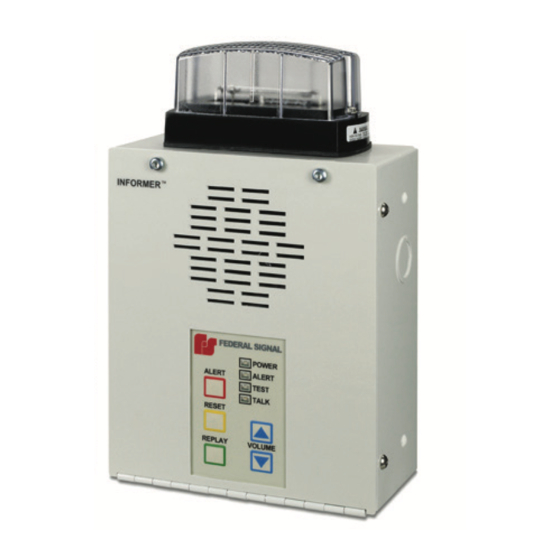
General Description General Description Introduction The Informer-IP Wall Mount is an intercom, a warning device, and an alarm initiation point that connects to an Ethernet network. An internal speaker is used to provide clear two-way voice communications between control and monitoring points and distributed locations. -
Page 8: Ordering Information
General Description • Local and remote volume level controls. • Informers are addressable Individually, in Groups, or All. • Requires minimal network bandwidth and uses TCP/IP protocol for security and reliability. • Remote supervision of Communications, Audio Output, Alert Function Execution. •... -
Page 9: Specifications
Specifications The following figure illustrates the wall mounted push buttons for activation. Figure 2 PS Series Push Button Stations (optional) Specifications Table 3 Specifications Operating Voltages at J2 9-15 Vdc using AC Transformer 108-128 Vac, 60 Hz with wall transformer Operating Current Standby: 9 V = <... -
Page 10: Installation
Installation Table 4 Compliance Electromagnetic Complies with FCC Title 47, Part 15 Interference FCC Part 15 Radio Frequency Interference (RFI) (FCC 15.105) Class B The Informer-IP Wall Mount was tested and found to comply with the limits for Class B digital devices pursuant to Part 15 Subpart B, of the FCC Rules. -
Page 11: Wall Mounting
Installation or external amplifiers and speakers may be required to provide adequate warning. 4. Position to keep the unit at least six inches away from the listener’s ears to avoid potential hearing damage. 5. Do not use near water; for example, near a bathtub, washbowl, kitchen sink, laundry tub, in a wet basement, near a swimming pool, rain or similar environments. -
Page 12: Recessed Mounting
Installation Recessed Mounting Before putting the Informer-IP in place, determine a suitable location considering the criteria listed in this manual. The Informer-IP has four holes for recessed mounting, two sets of two, located on the sides of the unit which accept #10 screws. Mounting location determines which set of holes are used or both. -
Page 13: Wiring The Device
Installation Wiring the Device SHOCK HAZARD: To reduce the risk of electric shock, disconnect AC power before connecting or removing AC power wires. Failure to heed this warning may cause serious injury or death. 1. Install this device by a qualified electrician in accordance with local and national electrical codes (NEC/CEC). -
Page 14: Figure 5 Internal Wiring For The Informer-Ip Wall Mount
Installation Figure 5 Internal Wiring for the Informer-IP Wall Mount STROBE OPTION STROBE 17500291 17500292 1751557 (JP8) KEYPAD Q3 C6 RED (N.O.2) RED (COM2) 2005062__ 2005062 R156 R153 C128 TO (J2) C100 1.6A POWER 1461179 (JP7) R150 SPKR LEVEL R149 C129 17500260 SPEAKER... -
Page 15: Memory Card Removal And Installation
Testing and Training Memory Card Removal and Installation The microSD card stores voice and tone messages. To remove the card: 1. Open front panel cover. 2. Find the microSD card. 3. Gently push card into the slot. The card can then be removed. To install the card: 1. -
Page 16: Controls
Operations Controls Table 5 Controls Button Description Volume Increases volume and beeps at the current volume level. Button Volume Decreases volume and beeps at the current volume level. Down Button ALERT The ALERT button sends an activation to the control points and changes the status icon to Red. -
Page 17: Audio/Relay - Input/Output Connections
Operations Description TALK The blue Talk LED flashes at a 1/10 second interval when a Live PA, Intercom Talk session, or Text-To-Speech message is in progress. The Talk LED turns on steady when the intercom monitor function is active. During an Intercom chat session, the local operator must listen while the blue LED is blinking and may talk when the LED is on steady. -
Page 18: Alert Rear Input
Operations A removable eight-position connector is located on the inside of the Informer-IP for making electrical connections. The connector accepts 3/16-inch (5 mm) stripped wire, 18-26 AWG. The 600 ohm audio output responds as the speaker does. Audio comes on with the speaker and is reset or shut off when the speaker audio shuts off. -
Page 19: Power Connector
Replacement Parts port auto-negotiates at 10/100 Mbps, full or half duplex connection. Power Connector The Informer-IP has an integral 120/240 Vac transformer. The transformer provides power to J2. Table 10 J2 Input Power (from transformer) Power connector Center – (9 to 15 Vdc) Outside –... -
Page 20: Getting Service
Getting Service Getting Service If you are experiencing any difficulties, contact Federal Signal Customer Support at: 800-548-7229 or 708-534-3400 extension 7511 or Technical Support at: 800-524-3021 or 708-534-3400 extension 7329 or through e-mail at: techsupport@fedsig.com. For instruction manuals and information on related products, visit: http://www.fedsig.com/ 2645 Federal Signal Drive University Park, Illinois 60484 www.fedsig.com...
Need help?
Do you have a question about the Informer-IP Wall Mount B Series and is the answer not in the manual?
Questions and answers