Table of Contents
Advertisement
Quick Links
Advertisement
Table of Contents

Related Manuals for Federal Signal Corporation Informer-IP C Series


Summary of Contents for Federal Signal Corporation Informer-IP C Series
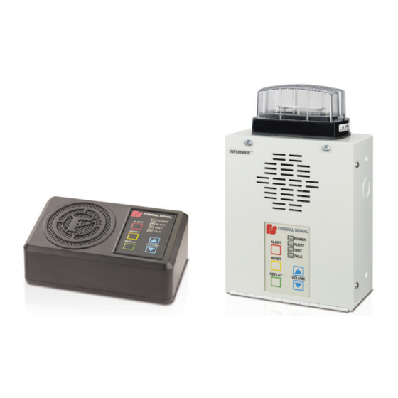
- Page 1 Informer-IP Series C Models: I-IP-IO, I-IPW, I-IP15, I-IP15X, I-IP100AC, I-IP100DC, I-IP100ACX, I-IP100DCX, I-IP2, I-IPSIU Setup, Program, and User Manual 25500395 Rev. C0 0920 Printed in U.S.A. © Copyright 2017-2020 Federal Signal Corporation...
- Page 2 A copy of this limited warranty can also be obtained by written request to Federal Signal Corporation, 2645 Federal Signal Drive, University Park, IL 60484, email to info@fedsig.com or call +1 708-534-3400.
-
Page 3: Table Of Contents
Contents Safety Messages..............................7 General Description ..............................7 Introduction .................................7 Informer Series C Overview............................8 Automatic Volume Level Control .........................8 Digital Inputs ...............................8 Informer SIP Telephone Interface ........................9 Informer Control using IP Phone Keypad ......................9 WAV File Control Commands ...........................10 Valid WAV File Control Commands ......................10 Invalid WAV File Control Commands ......................10 Function Control Commands .......................... - Page 4 Configuring Informers Using Commander Software (Optional) ...............35 1. Verify SmartMsg CenterPoint Software ......................35 2. Using SmartMsg CenterPoint Software ......................36 3. Configuring Security Key and Encryption Key (Optional) ................37 4. Configuring RTUs in Commander .........................38 Initial Informer Setup ..........................38 5. Uploading WAV Files to the Informers ......................41 6.
- Page 5 600-Ohms Audio Output ...........................79 Generating Alerts ..............................79 Configuring Inputs .............................79 Testing and Training ..............................80 Getting Service ..............................80 Appendix A Updating RTU Firmware ........................81 Appendix B Forms ..............................83 Appendix C Standard DV Messages ........................95 Setup, Program, and User Manual Federal Signal www.fedsig.com...
- Page 6 Tables Table 1 Input and Output Configuration .......................9 Table 2 Examples of Illegal WAV Files .........................10 Table 3 Examples of Illegal Function Control Commands ................11 Table 4 Coil Registers (1-9999) Read -Write ......................12 Table 5 Analog Output Holding Registers (40001-49999+) Read-Write ............13 Table 6 Commander Modbus Map ........................14 Table 7 Register Number (3x) ..........................14 Table 8 Register Number (4x) ..........................14...
-
Page 7: Safety Messages
Safety Messages Safety Messages It is important to follow all instructions shipped with this product. This device is to be installed by trained personnel who are thoroughly familiar with the country electric codes and will follow these guidelines as well as local codes and ordinances, including any state or local noise control ordinances. -
Page 8: Informer Series C Overview
Informer Series C Overview Informer Series C Overview The Federal Signal Informer series IP products incorporate industry-standard Web, SIP phone, and Modbus PLC interfaces to simplify integration with existing systems. The products can be purchased as part of a pre-integrated Commander ® IP solution with a touch screen HMI that can simplify configuring, controlling, and monitoring thousands of unique alert and notification scenarios. -
Page 9: Informer Sip Telephone Interface
Informer Series C Overview The digital inputs may also be configured using the Commander ® application. The Commander application will override web page configurations. Web page configurations must be applied and the Informer must be rebooted before the changes take effect. Table 1 Input and Output Configuration Product Family Number of Inputs Number of Outputs... -
Page 10: Wav File Control Commands
Informer Series C Overview is received or the 5 second character entry period expires, the framing character and any valid digits read are treated as noise and discarded. Leading 0 (zeros) digits are allowed, but not required. When a valid command is received, the Informer acknowledges the receipt by sending three short beeps, hanging up, and playing the WAV file or activating the function. -
Page 11: Function Control Commands
Informer Series C Overview Function Control Commands Function Control commands are used to activate functions that have been preconfigured into the Informer. Functions can be configured to control audio volume, activate relay outputs, play tones, and WAV files. Functions configured with Commander ® can also include delays and repeat loops. -
Page 12: Modbus Tcp
Informer Series C Overview Modbus TCP Modbus ® TCP can directly control and monitor speakers from an existing PLC over an Ethernet network. This interface provides direct control of WAV files and relay output(s) in the speaker. The interface also provides the ability to monitor the speaker’s digital inputs and activation status. -
Page 13: Notes
Informer Series C Overview Table 5 Analog Output Holding Registers (40001-49999+) Read-Write Analog Register Function Value Output data Number (4x) address 40001 Activate function code Function code number to activate 40002 Activate digital voice message (unit Digital voice message number to must be armed) activate 40003... -
Page 14: Modbus With Commander
Informer Series C Overview Modbus with Commander Modbus ® TCP can also be used to connect PLCs to the Commander ® HMI (Human Machine Interface). Commander can be used to configure the speakers over the network and provide control and status monitoring. Commander offers a configurable HMI that simplifies the activation of unique notification messages created with simplified touch screen menu selections for events, locations, actions, etc. -
Page 15: Commanderone Enabled
Informer Series C Overview • Automated activations • CommanderOne ® cloud interface CommanderOne Enabled CommanderOne is a secure cloud service offered by Federal Signal that allows remote communication with Commander through a website or the CommanderOne app for iPhone and Android ® mobile phones. CommanderOne Highlights: •... -
Page 16: Configuring Informers Using The Web Interface
Configuring Informers Using the Web Interface Configuring Informers Using the Web Interface Informer products can operate as autonomous devices controlled by contact closures without connecting to a network server or becoming part of a supervised network with remote configuration, control, and status monitoring. Use the Informer’s internal web server to configure network settings, volume control, remote input configuration, access security, Modbus ®... - Page 17 Configuring Informers Using the Web Interface Enter the default 10.10.10.1 IP address or the preconfigured static address for the Informer into your web browser to view the web page of the device. The Login window appears. Enter the Username: admin (or preconfigured Username) NOTE: If you change the Username or Password, record them in Appendix B “Table 11 Informer Network Configuration”...
- Page 18 Configuring Informers Using the Web Interface The Home page displays a summary of the current configuration settings for the RTU. The Navigation Menu (blue hyperlinks on left) is used to access other System Management web pages. Use the Help hyperlink to access the user manual from any web page.
-
Page 19: Changing The Network Settings
Configuring Informers Using the Web Interface Fields Description Up Time The elapsed time since power up or reboot. Record the MAC and IP address in Appendix B to ensure the device can be managed in the future. Changing the Network Settings You can configure the RTU to obtain an IP address automatically using DHCP and AutoIP, or you can assign a Static IP address. - Page 20 Configuring Informers Using the Web Interface Fields Description IP Address or The RTU’s assigned IPV4 address or its domain name in the IP Domain Name address field. Subnet Mask The RTU’s assigned subnet mask. Default The RTU’s network gateway for routing IP traffic Gateway Primary DNS The Primary Domain Name Server for the network (Must be entered if...
-
Page 21: Configuring The Rtu Settings
Configuring Informers Using the Web Interface 2. Configuring the RTU Settings When the RTU is used with Commander, the device’s RTU Number and Description need to be entered, and SmartMsg must be enabled. All devices in the system must have a unique RTU Number, and it should start with 001. - Page 22 Configuring Informers Using the Web Interface To change the configure the RTU Settings of the Informer: Select RTU Settings. The RTU Settings page appears. Informer-IP Series C Federal Signal www.fedsig.com...
- Page 23 Configuring Informers Using the Web Interface Fields Description General RTU Number The RTU’s assigned identity. When used on with a Commander network, all devices in the system must have a unique RTU Number. The number must be a positive integer. Description Use this 48-character text field to describe the RTU.
- Page 24 Configuring Informers Using the Web Interface Fields Description Modbus Enable Check to enable the Modbus interface. Modbus Modbus Port The RTU’s assigned Modbus TCP port number. The default is 502. Enable SIP Check to enable the SIP interface SIP Port The RTU’s assigned SIP port number.
- Page 25 Configuring Informers Using the Web Interface Fields Description Keepalive The keepalive interval in seconds. Enter a value between 10 and Interval 3600. The differentiated services code point value assigned to signaling messages from the RTU. Relay 1 Turns on Relay 1 when the input is active. Relay 2 Turns on Relay 2 when the input is active.
- Page 26 Configuring Informers Using the Web Interface Fields Description Priority The Priority assigned to the digital input. For Momentary mode, an input of equal or higher priority will interrupt an active Continuous mode input and will stop and over-ride currently active Momentary mode input.
-
Page 27: Configuring The User Setup
Configuring Informers Using the Web Interface 3. Configuring the User Setup User Setup allows Full Admin privileged users to create users, passwords, and assign security privileges. You cannot delete the Admin user or change the security privilege for the Admin user. You can change the Admin user’s username and password. - Page 28 Configuring Informers Using the Web Interface Fields Description Enable Check to enable the factory support user. When enabled, a hidden Factory static user and password is enabled for Federal Signal technical Support User support. You can disable this user. Apply Saves your settings.
-
Page 29: Uploading Certificates
Configuring Informers Using the Web Interface 4. Uploading Certificates Use the Certificates page to upload certificate files to support secure SIP TLS communication. Certificate files are optional, and if provided allow for CA certificate validation. File type Filename CA certificate ca-cert.pem Device SSL certificate cert.pem Device private key... -
Page 30: Uploading Firmware
Configuring Informers Using the Web Interface 5. Uploading Firmware Use the Upload Firmware page to load a new operating system into the Digi ® Ethernet module. The Home page displays the current version of the firmware. To upload new firmware: Select Upload Firmware. -
Page 31: Rebooting Device And Loading Configuration Settings
Configuring Informers Using the Web Interface 6. Rebooting Device and Loading Configuration Settings Use the Reboot page to reboot the device and load new configuration settings. To reboot the device and load new configuration settings: Select Reboot. The Reboot page appears. Click the Reboot button to reboot the device and load new configuration settings. -
Page 32: Restoring Configuration To Factory Defaults
Configuring Informers Using the Web Interface 7. Restoring Configuration to Factory Defaults You can restore the factory default settings with or without restoring the network parameters. Default Settings RTU Number: 1 Description: my description SmartMsg disabled Modbus disabled Smartmsg Server: 10.10.10.10 IP Address: 10.10.10.1 Subnet Mask: 255.255.0.0 Default Gateway: 10.10.10.10... -
Page 33: Restoring The Informer-Ip And I-Ipw To Factory Default
Configuring Informers Using the Web Interface If the configuration details are lost or changed incorrectly and it becomes necessary to restore the Informer to factory default settings, perform a Power-On Factory Default procedure. Restoring the Informer-IP and I-IPW to Factory Default The Informer-IP and I-IPW can be restored to the factory default by either using the web pages or the RESET button. -
Page 34: Logging Out Of The Web Interface
Configuring Informers Using the Web Interface service. 8. Logging Out of the Web Interface Use the Log Out page to log out before the five minute session timer expires. To log out of the web interface: Select Log Out. The Log Out page appears. Click the Log Out button to logout. -
Page 35: Configuring Informers Using Commander Software (Optional)
Configuring Informers Using Commander Software (Optional) Configuring Informers Using Commander Software (Optional) The Federal Signal Commander ® Software System is a software-based system that enables you to monitor, control, and activate your warning system. The following procedures are for setting up and programming the Informer with the Commander software. -
Page 36: Using Smartmsg Centerpoint Software
To verify the Informer is registered with the SmartMsg CenterPoint server: 1. Open the CenterPoint application. This application is typically installed under C:\Program Files (x86)\Federal Signal Corporation\CenterPoint Under the Users tab, each Informer that was added is displayed as a Siren_n. -
Page 37: Configuring Security Key And Encryption Key (Optional)
Configuring Informers Using Commander Software (Optional) 3. Configuring Security Key and Encryption Key (Optional) Security is an important part of any type of networking system. Federal Signal provides two types of security for Commander and Informers as defined below: • Security Key—Security keys are often used with radio-based systems, where two separate siren or informer networks are adjacent and there is concern that activation of one system might inadvertently activate the neighboring system. -
Page 38: Configuring Rtus In Commander
Configuring Informers Using Commander Software (Optional) Fields Description Security A 16-bit code (0-65535) that is programmed into each Informer and Commander control system. The Informer and Commander security key must match for successful communication. The Informer security key is programmed during initial programming and into Informers by using the Universal Programmer. - Page 39 Configuring Informers Using Commander Software (Optional) Select the unit to configure. 5. Click Configure. The Configure RTU General Parameters dialog box appears. Fields Description Station Displays the virtual RTU number of the RTU data currently being Number displayed. Use the spin box to select the next unit. Setup, Program, and User Manual Federal Signal www.fedsig.com...
- Page 40 Configuring Informers Using Commander Software (Optional) Fields Description Station Name This data field contains the RTU name. This is usually a local or familiar name of the location of the RTU. The format of this data entry field is any alphanumeric data from 0 to 30 characters long.
-
Page 41: Uploading Wav Files To The Informers
Identify or create a folder on your hard drive where your custom WAV files are stored. For example, create a folder named Custom WAV Files in the following directory: C:\Program Files\Federal Signal Corporation\Sfcdware\data\Custom Files NOTE: The WAV files must be mono, 8 bit, 8 kHz format. - Page 42 Configuring Informers Using Commander Software (Optional) NOTE: See the Mute audio during upload field in table, which prevents audio from being broadcast over other audio equipment, such as amplified speakers. To upload WAV files to the Informer: From the Commander main window, click RTU. The RTU dialog box appears.
- Page 43 The Open dialog box appears. 6. If you created a custom folder, select your WAV files from the following directory: C:\Program Files\Federal Signal Corporation\Sfcdware\data\Custom Files Click Open. NOTE: Use the table in Appendix B to record the WAV file number, name, message, and length.
- Page 44 Configuring Informers Using Commander Software (Optional) IMPORTANT: If you are unsure of the number and content of messages currently programmed, Federal Signal recommends deleting existing messages when starting a new upload. The upload would then include all messages. After clicking Upload All, the Delete existing messages dialog box appears. Click either Yes, No, or Cancel.
- Page 45 Configuring Informers Using Commander Software (Optional) The following table describes additional selections in the Digital Voice Upload programming. Fields Description Duration of The total duration of all messages displays at the bottom of the screen. Messages Series C Informers can store over four hours of audio. Series A and B Informers have 15-minute storage capacity.
-
Page 46: Programming Functions
Configuring Informers Using Commander Software (Optional) 6. Programming Functions Functions are a set of specific instructions for an Informer device. A function can be as simple as turning on a relay for 5 seconds or broadcasting a WAV file. Functions typically use a WAV file;... -
Page 47: Creating Functions
Configuring Informers Using Commander Software (Optional) To name a Function: Open the System Setup dialog box. In the Code Name/Duration section, double-click the row you want to change. The Enter Code Name dialog box appears. Enter Name and Duration, and then click Save. Creating Functions To create functions: From the Commander main window, click RTU. - Page 48 Configuring Informers Using Commander Software (Optional) Fields Description Program Displays the number of program entries that are currently stored in Entries memory. This number is zero if no program entries are currently stored in memory. Function Contains a list of available functions. Select To add a function, select the desired function, and then click Add >.
- Page 49 Configuring Informers Using Commander Software (Optional) The Send Message to RTU dialog box appears. Fields Description Clear Clears the activation and cancel counters for this RTU. Counters General Sends the following items from the General Parameters screen: Parameters • Alarms: Enabled/Disabled. •...
-
Page 50: Table 9 Function Definitions
Configuring Informers Using Commander Software (Optional) The following table list the Functions with their descriptions. Table 9 Function Definitions Fields Description The Arm function activates the amplifier in an Informer. The Informer must be armed or activation functions will not operate. Once armed, the Informer remains armed for approximately 4-1/2 minutes. - Page 51 Configuring Informers Using Commander Software (Optional) Fields Description Delay Delays for a fixed number of seconds. Enter the desired delay time, and then click OK. This function inserts a delay into the function. For example: Activate a relay to turn on a strobe, delay 10 seconds, and then sound voice message alert.
-
Page 52: Copying Functions From Another Rtu
Configuring Informers Using Commander Software (Optional) Fields Description Repeat Start –n Enter the desired number of times to repeat, then and click OK. Repeat End All functions between Repeat Start and Repeat End will repeat n times. Enter between 0-255. WARNING: Do not attempt to use the repeat functions on legacy RTUs. -
Page 53: Configuring Zones
Configuring Informers Using Commander Software (Optional) 7. Configuring Zones Zones allow many Informers to share a common name. This can simplify activations for commonly used groups. You can use zones for physical groupings such as floors (for example, zone 1 = floor 1, zone 2 = floor 2). Zones can also be named to allow for ease of selection during events. - Page 54 Configuring Informers Using Commander Software (Optional) The Zone Setup dialog box appears. Fields Description Zone # Displays the zone number. Zone Enter the name of the zone. Name Individual Contains a list of all sites in your system. Sites Zone Click either Zone Group A or Zone Group B.
-
Page 55: Creating Activation Templates
Configuring Informers Using Commander Software (Optional) 8. Creating Activation Templates Activation Templates are preset events, which specify sites (Informers) and/or zones with functions. Activation Templates can include sounding sirens, sending smart messages, sending text to a scrolling message display and mass notification. When created, you can associate activation templates with Informer inputs. - Page 56 Configuring Informers Using Commander Software (Optional) The Program Activation Template dialog box appears. Fields Description Individual Contains a list of all sites in your system. Zone Group Zone Group A and Zone Group B contain preconfigured zones. Zones are a grouping of sites defined using the Zone Setup dialog box. Function Displays the function to be sounded.
- Page 57 Configuring Informers Using Commander Software (Optional) Fields Description Add > Adds selected sites or zones in your system to the Destination RTU list. Add All > Adds all sites in your system to the Destination RTU list. < Remove Removes selected or all sites. <...
- Page 58 Configuring Informers Using Commander Software (Optional) Fields Description Display Tab Informer devices contain a Display tab to configure the operation of a scrolling message display. The scrolling message display is an optional accessory that attaches to the Informer to display text messages on a large overhead LED display.
-
Page 59: Configuring Input Options
Configuring Informers Using Commander Software (Optional) Select Auto-Poll after Activation for Commander to poll each site after sending the activation command. Allows system status to be automatically updated after alerts. 8. Optional: Click Select Message to add to a list of digital voice messages to be played during the DYNAMIC VOICE function. - Page 60 Configuring Informers Using Commander Software (Optional) The following is an example of the Informer Input Options dialog box. Fields Description Name Allows you to change the name of the Informer inputs. The assigned name appears on the Status Detail screen and all Smart Messages and emails associated with the respective input.
-
Page 61: Local Activation Inputs (Informer15 And Informer100)
Configuring Informers Using Commander Software (Optional) Fields Description Activation Activation Template can be associated with Informer inputs. Template If Activation Templates were created, they are available for selection in the list. To create, edit, and manage Activation Templates, select Tools > Activation Templates from the main menu. Polarity To set the input polarity, click the down arrow and select either Normally Open or Normally Closed. - Page 62 Configuring Informers Using Commander Software (Optional) The Program dialog box appears. 5. For Input 1, go to the Function Number to be assigned to the input. Use the arrow buttons to scroll through programed functions. Fields Description Unit Type Displays the unit type. Unit Displays the unit address.
-
Page 63: Configuring Hot Keys
Configuring Informers Using Commander Software (Optional) In the Mode list, click either Momentary or Continuous. 8. In the Polarity list, click either Normally Open or Normally Closed. Click Save to save the Input-to-function assignment, Mode, and Polarity. 10. Repeat steps 4 through 6 for Inputs 2, 3, and 4 if applicable. 11. - Page 64 Configuring Informers Using Commander Software (Optional) A Warning dialog box appears. Click OK. The Activation Hot Keys dialog box turns red, which indicates that the hotkeys are now programmable. NOTE: Commander remains in programing mode for 15 seconds. Click the key you want to configure. The Program Hotkey dialog box appears.
-
Page 65: Programming Listening Options
Configuring Informers Using Commander Software (Optional) Click Add All to sound all sites in your system. All Sirens appears in the Destination RTU field. 8. Select from the Function list. NOTE: Use the table in Appendix B to record information Click Save. - Page 66 Configuring Informers Using Commander Software (Optional) To configure an Informer with unique settings for listening: Select the Informer to configure. Select Configuration > Listen Options. The Informer Listen options dialog box appears. All three modes allow optional recording. Recording is selected from the main Informer dialog box.
-
Page 67: Configuring Informer15 And Informer100 Pa (Voip) Settings
Configuring Informers Using Commander Software (Optional) 12. Configuring Informer15 and Informer100 PA (VoIP) Settings The Informer15 and Informer100 devices have PA (VoIP) settings for sound power during public address announcements. The power attenuation allows the sound output to be attenuated up to 20 dB for PA. For example, if set to -10 dB the sound output of the speaker will be lowered from the maximum by 10 dB. -
Page 68: Configuring The I-Ipsiu Radio Settings
Configuring Informers Using Commander Software (Optional) 14. Configuring the I-IPSIU Radio Settings The Informer Sensor Interface Unit (I-IPSIU) uses the audio out interface for broadcast of alerts to radio systems. The audio output is a 600-ohm interface with manual volume control. - Page 69 Configuring Informers Using Commander Software (Optional) Fields Description Voice under-run delay Underrun occurs when a device runs out of data during (seconds) live streaming PA or VOIP causing the audio to cut out, also known as buffering. To mitigate buffering the under- run delay setting allows playback to be delayed by a fixed duration to allow the device to accumulate data before playback begins.
-
Page 70: Using Informer Intercom
Using Informer Intercom Using Informer Intercom Use the intercom function to provide bi-directional voice communications between the Informer and the Emergency Operations Center (EOC) control point. The EOC can talk to one or many units at the same time, but you can only listen to or record from one device at a time. - Page 71 Using Informer Intercom Fields Description Intercom Displays the current operating state of the Intercom. There are three Status window possible states: Standby, Talking and Listening. Intercom Log Displays all Intercom communication activity including which device is window being communicated with. The user can scroll through the entries. Command Log Appears automatically on the bottom center of the screen when display...
-
Page 72: Using The Public Address System
Using the Public Address System Fields Description Playback Allows the control point operator to view all recorded calls and select Audio Button any recorded call for playback. When the EOC is talking, the Informer can listen but not talk. The EOC is in control of which Informer is included in the call and when the Informer can talk or listen. -
Page 73: Broadcasting Messages
Using the Public Address System Broadcasting Messages To broadcast a message using the microphone connected to the PC with Commander: From the Commander main window, select Activate > PA (VOIP). The PA (VOIP) dialog box appears. Fields Description PA Text to Enter your message to play. - Page 74 Using the Public Address System Fields Description VU Peek Adjust the Microphone level so the VU Peek Meter sweeps full scale Meter on voice peeks. The VU Peek meter is color coded as follows: Green: Level below peek Yellow: One or more samples at or above peek. Red: More than 5% of samples at or above peek.
-
Page 75: Broadcasting Wav Files
Select a WAV file for public address transmission. Most SPSF WAV file formats are supported. If you created a custom folder, select your WAV files from the following directory: C:\Program Files\Federal Signal Corporation\Sfcdware\data\Custom Files Click Open. The Select Sites to Activate dialog box appears. -
Page 76: Broadcasting Text To Speech (Tts)
Using the Public Address System Broadcasting Text to Speech (TTS) To broadcast a Text to Speech message from the PC with Commander: From the Commander main window, select Activate > PA (VOIP). The PA (VOIP) dialog box appears. Enter your text to speech message in the PA Text to Speech text box on the left side of the window. -
Page 77: Using The Informer-Ip
Using the Informer-IP Using the Informer-IP When the Informer-IP receives an alert message or an alert tone, the red Alert LED begins to flash, and audio is heard over the speaker. The audio sends out the optional 600 ohms audio output, and the output relays close as programmed. The alert messages and WAV files are recorded and stored in memory until the alert is reset. -
Page 78: Dual Relay
Using the Informer-IP The control points can override the local volume controls with remote volume control commands. If no volume control commands are issued from the control points, the local volume level is heard. Control points should always issue Emergency Alerts using a High- Power command to ensure all users hear the alert. -
Page 79: 600-Ohms Audio Output
Using the Informer-IP 600-Ohms Audio Output The 600-ohms audio output is useful for tying the Informer-IP and Informer-PA into existing public address (PA) systems or other externally amplified speaker systems. The I-IPSIU audio output is used to interface radio systems. An adjustable balanced audio output is available at pins 1 and 2 of the output connector. -
Page 80: Testing And Training
Testing and Training Testing and Training After the installation is complete: • Test the Informer and all accessories from the control point(s) to ensure it is operating properly. • Ensure all users are properly trained to use the system before putting the Informer into service. -
Page 81: Appendix A Updating Rtu Firmware
Appendix A Updating RTU Firmware Appendix A Updating RTU Firmware To update the RTU firmware, do the following from Commander: Select Tools > Update RTU Firmware. The following dialog box appears. Fields Description Sites Displays the RTUs you can program. NOTE: Each model requires different software;... - Page 82 Appendix A Updating RTU Firmware 5. Click Send. The following Warning window appears. 6. Click OK to continue. Click Quit to exit the dialog box. Informer-IP Series C Federal Signal www.fedsig.com...
-
Page 83: Appendix B Forms
Appendix B Forms Appendix B Forms Table 11 Informer Network Configuration Domain Name IP Address Subnet Mask Default Gateway Primary DNS Server Alternate DNS Server SMTP Server Name (optional) SMTP Server Address (optional) SmartMsg Parent Server Name SmartMsg Parent Server Name/Address Failover Server 1 Name/Address Failover Server 2 Name/Address Failover Server 3 Name/Address... -
Page 84: Table 12 Network Device
Appendix B Forms Table 12 Network Device Name/Location IP Address x.x.x.x Site ID# xxx xx:xx:xx:xx:xx:xx Control Station 1 Control Station 2 Control Station 3 Device Name Informer-IP Series C Federal Signal www.fedsig.com... - Page 85 Appendix B Forms Name/Location IP Address x.x.x.x Site ID# xxx xx:xx:xx:xx:xx:xx Setup, Program, and User Manual Federal Signal www.fedsig.com...
-
Page 86: Table 13 Wav File Messages (Dv Messages)
Appendix B Forms Table 13 WAV File Messages (DV Messages) WAV File Name Message and Description Length Number Informer-IP Series C Federal Signal www.fedsig.com... -
Page 87: Table 14 Programed Functions
Appendix B Forms Table 14 Programed Functions Function Number Program Entries Definition Function Name Function Number Function Name Function Number Function Name Function Number Function Name Setup, Program, and User Manual Federal Signal www.fedsig.com... -
Page 88: Table 15 Programed Zones
Appendix B Forms Table 15 Programed Zones Zone Zone Name Sites in this Zone Number A/B Informer-IP Series C Federal Signal www.fedsig.com... -
Page 89: Table 16 Programed Activation Templates
Appendix B Forms Table 16 Programed Activation Templates Template Template Name Action Number Setup, Program, and User Manual Federal Signal www.fedsig.com... -
Page 90: Table 17 Input Programming Informer
Appendix B Forms Table 17 Input Programming Informer RTU # Name Call Audible SmartMsg Activation Request Template Template Informer-IP Series C Federal Signal www.fedsig.com... -
Page 91: Table 18 Hot Keys
Appendix B Forms Table 18 Hot Keys Name Action Number Setup, Program, and User Manual Federal Signal www.fedsig.com... - Page 92 Appendix B Forms Name Action Number Informer-IP Series C Federal Signal www.fedsig.com...
-
Page 93: Table 19 Informer Input Configuration
Appendix B Forms Table 19 Informer Input Configuration Input __ Mode Polarity Function List Definition Momentary Normally Open Continuous Normally Closed Input __ Mode Polarity Function List Definition Momentary Normally Open Continuous Normally Closed Input __ Mode Polarity Function List Definition Momentary Normally Open... - Page 94 Appendix B Forms Input __ Mode Polarity Function List Definition Momentary Normally Open Continuous Normally Closed Input __ Mode Polarity Function List Definition Momentary Normally Open Continuous Normally Closed Input __ Mode Polarity Function List Definition Momentary Normally Open Continuous Normally Closed Informer-IP Series C Federal Signal www.fedsig.com...
-
Page 95: Appendix C Standard Dv Messages
Appendix C Standard DV Messages Appendix C Standard DV Messages Table 20 Standard DV Messages FWS Name Customer Name Description Notes for DV FWS-13955 TM1 (5 sec) Wail-Conventional Siren 560-1055 Hz FWS-13956 TM2 (5 sec) Yelp-Rapid Siren 560-1055 Hz FWS-13957 TM3 (5 sec) High-Low-Alternating High and Low 561 Hz and 760 Hz FWS-13958 TM4... - Page 96 Appendix C Standard DV Messages FWS Name Customer Name Description Notes for DV FWS-13982 TM28 (5 sec) Ringer-Continuous Ringing Tone 560 Hz and 326 Hz FWS-13983 TM29 (5 sec) Buzzer-Buzzer Tone 1318 Hz and 760 Hz FWS-13984 TM30 (5 sec) Attention-Extremely Rapid Siren-Multiple Frequency FWS-13985 TM31 (5 sec) Multi-Tone-Extremely Rapid Siren-...
- Page 97 Appendix C Standard DV Messages FWS Name Customer Name Description Notes for DV FWS-14007 Severe Weather This is a severe weather warning. Take shelter Warning-Seek immediately. Repeat, severe weather warning. Shelter Take shelter immediately. FWS-14008 Severe Weather “Please take shelter immediately. This is a Alert-Seek Shelter severe weather alert.”...
- Page 98 Appendix C Standard DV Messages FWS Name Customer Name Description Notes for DV Lightning FWS-14021 Lightning- Take Dangerous lightning in the area. Take shelter shelter immediately. Repeat, dangerous lightning in the area. Take shelter immediately. Armed Person/ Intruder/ Dangerous Situation/Security Alert FWS-14022 Dangerous Situation “Attention.
- Page 99 Appendix C Standard DV Messages FWS Name Customer Name Description Notes for DV FWS-14035 Hazmat-Seek “Attention. Attention. Hazardous condition. Seek Shelter shelter immediately and wait for the all clear.” Evacuate FWS-14036 Evacuate To Safe “Attention! Evacuate to a safe area.” Area FWS-14037 Emergency “Warning, this is an emergency evacuation order.
- Page 100 Appendix C Standard DV Messages FWS Name Customer Name Description Notes for DV Fire FWS-14049 Fire-Wild Land Fire “Wild land fire approaching. Remain calm and evacuate campus.” FWS-14050 Fire Drill “Attention this is a fire drill, report to your designated area.” FWS-14051 Fire Alert “Attention this a fire alert, report to your designated area.”...
- Page 101 Appendix C Standard DV Messages FWS Name Customer Name Description Notes for DV FWS-14068 Army Song “The Army Goes Rolling Along” FWS-14069 National Anthem National Anthem 80 sec. Armed Forces Sounds -Bugle Call FWS-14070 “Adjutant’s Call” “Adjutant’s Call” FWS-14071 Assembly “Assembly”...
- Page 102 Appendix C Standard DV Messages FWS Name Customer Name Description Notes for DV FWS-14100 Chime Test Tone Chime Test Tone FWS-14101 Continuous Tone Continuous Tone PFEER Toxic Gas Alarm 1 kHz PFEER Toxic Gas signal Alarm 1 kHz signal FWS-14102 Duck and Cover Duck and Cover FWS-14103 Emergency Emergency Shutdown...
Need help?
Do you have a question about the Informer-IP C Series and is the answer not in the manual?
Questions and answers