
Subscribe to Our Youtube Channel
Related Manuals for REMKO ATY 260


Summary of Contents for REMKO ATY 260
- Page 1 REMKO ATY ATY 260, ATY 350 Wall - room air conditioner in split design Operation · Technology · Spare parts Edition GB – T08...
-
Page 3: Table Of Contents
Read these operating instructions carefully before start up / use of units! These instructions are part of the unit and must always be stored in immediate vicinity of the placement location or on the unit. Made by REMKO Changes reserved; no liability for errors or printing errors! -
Page 4: Safety Guidelines
„Start up protocol“ and returned eliminate danger from the unit it to REMKO GmbH & Co. KG . The units and components may for personnel. The warranty conditions are listed ■... -
Page 5: Transport And Packaging
Unit description Circuit diagram - coolant circuit - interior unit The room air conditioning units Evaporator fan ATY 260-350 have a REMKO ATY...AT exterior section as well as Connection - suction line an interior unit ATY...IT. The exterior section is used in... -
Page 6: Operation
REMKO ATY Operation The interior unit can be comfortably operated with the standard infrared remote control. The proper data transfer is confirmed by the interior unit with a signal sound. If programming via the infrared remote control is not possible, then the interior unit can also be operated manually. - Page 7 Buttons of remote control 2. Cooling mode „ “ (SWING) button In this mode, the cold air in the This button directly activates room is cooled down to the the oscillating function of the desired temperature. fins for better air distribution in the room.
- Page 8 REMKO ATY Button functions The transmission of the settings is shown by a symbol in the display. ON/OFF Button By pressing the ON / OFF button, you can activate or deactivate your unit. The programmed settings and adjustment values before the unit was turned off will appear in the display.
- Page 9 In automatic mode, the regulation autonomously selects between heating AUTOMATIK mode and cooling operation, when the unit is first turned on. A nominal temperature of 24 °C is preset. The regulating range is between 22 °C and 26 °C. It can be increased or decreased by 1 °C with buttons /. The fan speed cannot be changed.
- Page 10 REMKO ATY In the dehumidification mode, the room temperature can be adjusted DEHUMIDIFICATION MODE between 18 °C and 30 °C. Due to the low temperature of the refrigerant, the dew point of the air on the condenser is lower. The excess moisture in the air is condensed on the condenser, the room is dehumidified.
- Page 11 With the button a programming function is activated, which causes SLEEP button (covered) the nominal temperature in the cooling mode to increase after one hour by 1 °C and after 2 hours by 2 °C . In the heating mode, the nominal temperature is decreased after one hour by 1 °C and after 2 hours by 2 °C.
- Page 12 REMKO ATY PROGRAMMING TIMER OFF TIMER Programmed time reached Unit out of operation The regulation turns the unit on or off after programming. In operation, PROGRAMMING TIMER ON/OFF all settings are visible on the display. Out of operation, only the timer settings are visible.
- Page 13 The unit determines the actual temperature inside the wall unit. The I FEEL button (covered) temperature near the remote control may deviate from that setting. With the button, the temperature measured on the remote control is transmitted to the wall unit, the nominal temperature does not change. A continuing temperature reconciliation with the actual current temperature of the remote control is made approx.
-
Page 14: Shut Down
Cleaning the filter on the Contact REMKO GmbH & Co. unit. interior unit KG or your contract partner for companies near you. - Page 15 2. Open the lower display cover on the front side of the unit Type of work by pressing both latches and carefully fold the cover Check / maintenance / inspection downward and remove it from the bracket (Fig. 3). • •...
-
Page 16: Troubleshooting And Customer Service
REMKO ATY Troubleshooting and Customer service The units and components are manufactured with the most up-do-date manufacturing methods and are checked several times for proper function. However, should a functional problems occur, please check the function according to the chart below. When all functional checks have been completed and the unit still does not work... - Page 17 Problem display by blinker code Display Cause What to do ? 88 blinks Loss of power for 3 minutes Turn off and on again E1 blinks Communication error Display regulation Contact dealer E2 blinks Air circulation sensor on interior unit is defective / triggered Contact dealer E3 blinks Antifreeze sensor interior unit defective / triggered...
-
Page 18: Assembly Instructions For Technicians
REMKO ATY Installation instructions for technicians Important notes before Select the installation location If the single length of the ■ ■ installation to ensure clear air input and refrigerant lines exceeds output. (See section „Minimum 5 meters, then refrigerant has NOTE clearances“). - Page 19 Wall openings Selection of the installation Wind location A wall opening of at least 70 If the unit is installed in windy ■ mm diameter and 10 mm slope The interior unit is designed for areas, then it should be ensured from the inside to the outside horizontal wall installation in the that the building discharged warm...
- Page 20 1000 be provided for maintenance and Air inlet 1000 repair work and for optimum air distribution. 1000 discharge 1000 ATY 260 AT ATY 350 AT 100 mm 100 mm 700 mm 700 mm 400 mm 400 mm 100 mm 100 mm...
-
Page 21: Installation
Installation Oil return measures NOTE Open display cover The installation may only If the exterior unit is located at a be made by authorized higher level than the interior unit, technicians. then suitable oil return measures must be made. This is usually done by fabricating an oil lift fitting, which is to be installed for each Unit installation... - Page 22 REMKO ATY Connection of 4. Route the refrigerant lines from 12. Then tighten the fittings with refrigerant lines the interior unit to the exterior 2 properly sized open-ended unit. Make sure they are wrenches. The on site connection of the...
-
Page 23: Leakage Test
Leakage test Deburring the refrigerant line When all connections are made, The duration of the vacuum the pressure gauge station is creation depends on the pipe line Refrigerant line connected to the corresponding volume of the interior unit and Schrader valve connections, if the length of the refrigerant lines, present: however, the procedure takes at... -
Page 24: Condensation Connection
REMKO ATY Condensation Electrical connection connection The condensation hose is designed A power line must be installed as Due to the dew point shortfall on to be installed on the right and the power supply to the interior unit the evaporator, condensation is left side (view from front). -
Page 25: Electrical Circuit Diagram
NOTE Check all electrical plug and terminal connections for tight and permanent seating, retighten, if necessary. Electrical wiring schematic ATY 260 / ATY 350 Exterior section Interior unit Power supply line External conductor 230 V~, 50 Hz,... -
Page 26: Electrical Connection Diagram
REMKO ATY Electrical wiring schematic Check the refrigerant lines and ■ ATY 260 AT / ATY 350 AT insulation for damage. Reverse valve Check the electrical connection ■ Evaporator fan between the interior unit and the exterior unit for correct... -
Page 27: Start Up
Start up Function test of Cooling 9. Check the function of the NOTE operating mode condensation line by pouring The start up may only be distilled water into the made by especially trained 1. Remove the caps on the valves. condensation pan. -
Page 28: Unit Dimensions
REMKO ATY Unit dimensions ATY 260 AT / ATY 350 AT All measurements in mm ATY 260 IT / ATY 350 IT All measurements in mm Dimensional and design changes to advance technical progress are reserved. -
Page 29: Technical Data
1/4 (6,35) (mm) Refrigerant connection - suction line Inch 3/8 (9,52) 1/2 (12,7) (mm) Associated interior unit ATY 260 IT ATY 350 IT Operating range °C +16 to +32 +16 to +32 Adjustment range - Cooling °C +18 to +30... -
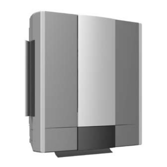
Page 30: Product Illustration
REMKO ATY Unit illustration ATY 260 IT / ATY 350 IT Dimensional and design changes to advance technical progress are reserved. Spare parts list Description ATY 260 IT ATY 350 IT Cover - air inlet 1107400 1107400 Cover - display... - Page 31 Product illustration ATY 260 AT / ATY 350 AT Dimension and design changes to advance technical progress are reserved. Spare parts list Description ATY 260 AT ATY 350 AT Front wall 1107421 1107421 Fan blade, evaporator 1107422 1107422 Fan motor, evaporator...
- Page 32 This has earned the reputation that we are more than only a good, reliable supplier: REMKO, a partner who finds a solution to any problem. Sales REMKO provides not only a well-established distribution...
Need help?
Do you have a question about the ATY 260 and is the answer not in the manual?
Questions and answers