
Subscribe to Our Youtube Channel
Related Manuals for REMKO ATY Series


Summary of Contents for REMKO ATY Series
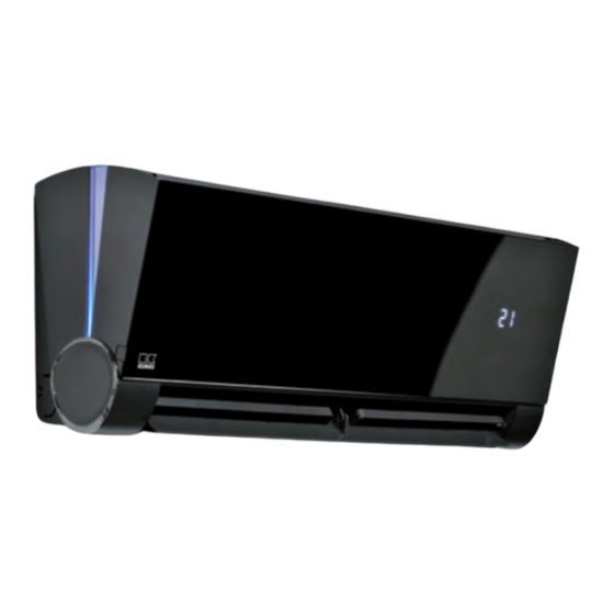
- Page 1 Assembly and operating instructions REMKO ATY ATY 265, ATY 355, ATY 525 Inverter wall - room air conditioner in multisplit design Read the instructions prior to performing any task! 0127-2017-08 Edition 1, en_GB...
- Page 2 Read these operating instructions carefully before commis- sioning / using this device! These instructions are an integral part of the system and must always be kept near or on the device. Subject to modifications; No liability accepted for errors or mis- prints! Installation and operating instructions (translation of the orig- inal)
-
Page 3: Table Of Contents
Table of contents Safety and usage instructions......................4 1.1 General safety notes........................4 1.2 Identification of notes........................4 1.3 Personnel qualifications........................4 1.4 Dangers of failure to observe the safety notes................4 1.5 Safety-conscious working....................... 4 1.6 Safety notes for the operator......................5 1.7 Safety notes for installation, maintenance and inspection.............. -
Page 4: Safety And Usage Instructions
REMKO ATY Safety and usage instructions CAUTION! This combination of symbol and signal word 1.1 General safety notes warns of a potentially hazardous situation, which if not avoided may cause injury or mate- Carefully read the operating manual before com- rial and environmental damage. -
Page 5: Safety Notes For The Operator
"certificate of warranty" to conditions stipulated in this manual and comply REMKO GmbH & Co. KG at the time when the with all applicable regional regulations. units are purchased and commissioned. -
Page 6: Transport And Packaging
REMKO ATY 1.11 Transport and packaging The devices are supplied in a sturdy shipping con- tainer. Please check the equipment immediately upon delivery and note any damage or missing parts on the delivery and inform the shipper and your contractual partner. For later complaints can not be guaranteed. -
Page 7: Technical Data
Technical data 2.1 Unit data Series ATY 265 ATY 355 ATY 525 Design-Wall unit for inverter multisplit outdoor Operating mode units for cooling and heating 2.64 3.52 5.28 Nominal cooling output 2.93 3.81 5.57 Nominal heat capacity Application area (room volume), approx. Adjustment range room temperature °C +17 to +30... -
Page 8: Unit Dimensions
REMKO ATY Series ATY 265 ATY 355 ATY 525 Dimensions Height Width 1004 Depth Weight 13.0 Serial number EDP no. 1623230 1623233 1623236 Air inlet temperature TK 27°C / FK 19°C, outside temperature TK 35°C / FK 24°C, max. air volume, 5m pipe length in combination with MVT outdoor unit Air inlet temperature TK 20°C, outside temperature TK 7°C / FK 6°C, max. -
Page 9: Design And Function
3: Suction pipe connection rator fan, controller and condensate tray. The 4: Injection pipe connection indoor unit can be combined with REMKO outdoor units from the series MVT 602-1402 DC that pro- vide sufficient cooling capacity. The outdoor unit is 3.2 Combinations... -
Page 10: Operation
REMKO ATY Operation 4.1 General notes Alarms are indicated by a code (see chapter The indoor unit is easily operated using the Troubleshooting and customer service). standard infrared remote control. The indoor unit beeps to acknowledge the correct transmission of data. -
Page 11: Keys On The Remote Control
4.3 Keys on the remote control "SLEEP" key Activates/deactivates the "SLEEP" function. Pressing this key will automatically increase or decrease the target temperature by 1 °C within an hour in cooling mode and heating mode respec- tively. Press this key to maintain the most conven- ient temperature and save energy. - Page 12 REMKO ATY “SILENCE/FP” key "FOLLOW ME" key Activates/deactivates the silent mode. Pressing the This key can be used to activate/deactivate the key for longer than 2 seconds activates the unit's FOLLOW ME function. In this mode, the room tem- frost protection function.
- Page 13 Indicators on the LCD The illustration of the LCD with all of the sym- bols present is only intended to provide a clearer overview. During operation, only those symbols relevant to the respective functions appear on the display. Key functions A symbol is shown on the display to indicate that the settings are being transferred.
- Page 14 REMKO ATY "Dehumidification" mode Wichtiger Hinweis Make sure that the indoor unit is connected to the power supply, and is switched on. Im "Automatik"-Modus wählt das Klimagerät automatisch zwischen dem Kühl-, Umluft- und The operating mode indicator on the display of the Heizbetrieb.
- Page 15 "Timer" mode Setting the “switch-off time” Press the "TIMER ON" key to set the "switch-on Press the "TIMER OFF" key. The remote time" and the "TIMER OFF" key to set the "switch- control shows "TIMER OFF", the last "switch- off" time for the unit. off time"...
- Page 16 REMKO ATY Example TIMER function settings Combined TIMER (setting "TIMER ON" and "TIMER OFF" at the same time) "TIMER ON" (Auto on mode) "TIMER OFF ð "TIMER ON" Example: (On ð Stop ð Start) You want the air conditioning unit to switch on 2 hours from the time it was programmed.
- Page 17 "TIMER ON ð "TIMER OFF" SLEEP function (Off ð Start ð Stop) The sleep function saves energy while you sleep. This function is activated by pressing the key on Example: the remote control. Press the key before going to sleep. In cooling mode, the unit automatically You want the air conditioning unit to switch on in increases the set room temperature by 1 °C after 1 two hours from the time it was programmed, and...
-
Page 18: Installation Instructions For Qualified Personnel
REMKO ATY Installation instructions for qualified personnel 5.1 Important notes prior to instal- 5.2 Installation materials lation The indoor unit is attached to the wall by a wall bracket and 4 screws (to be provided by the cus- Observe the operating manuals for the indoor unit tomer). -
Page 19: Minimum Clearances
5.4 Minimum clearances Observe the minimum clearances to allow access for maintenance and repair work and facilitate optimum air distribution. 1600 Fig. 18: Minimum clearances 1: Air inlet 2: Air outlet 5.5 Connection variants for the indoor unit The following connection variants can be used for the refrigerant, condensate and control lines. Fig. -
Page 20: Connection Of The Indoor Unit When The Refrigerant Piping Is Installed Under The Plaster
REMKO ATY 5.6 Connection of the indoor unit when the refrigerant piping is installed under the plaster If the customer routes the refrigerant piping to the unit underneath the plaster, observe the following note. The principal connection options can be found in the "Connection variants for the indoor unit" and "Wall bracket"... -
Page 21: Wall Bracket
5.7 Wall bracket Fig. 21: Wall bracket for indoor units ATY 265-525 IT (rear view) Dimensions (mm) ATY 265-355 IT ATY 525 IT We reserve the right to modify the dimensions and design as part of the ongoing technical development process. -
Page 22: Installation
REMKO ATY Installation Connection of refrigerant piping The refrigerant piping is connected (responsibility Unit installation of the customer) on the back side of the unit. It may be necessary to fit a reducer or flared NOTICE! adapter to the indoor unit. These fittings are included with the indoor unit as an accessory kit. -
Page 23: Condensate Drainage Connection And Safe Drainage
Condensate drainage connection and safe NOTICE! drainage Local regulations or environmental laws, for example the German Water Resource Law Condensate drainage connection (WHG), can require suitable precautions to pro- tect against uncontrolled draining in case of If the temperature falls below the dew point on the leakage to provide for safe disposal of escaping evaporator, condensation will form on the indoor refrigerator oil or hazardous media. -
Page 24: Electrical Wiring
REMKO ATY Electrical wiring 8.1 General notes Make the connection as follows: Open the air inlet grill. A protected power supply cable is to be connected to the outdoor unit and 4-core control line is to be Remove the covers on the right-hand side connected to the indoor unit respectively. -
Page 25: Electrical Wiring Diagram
8.2 Electrical wiring diagram Connection MVT 602-1402 DC L(1) 2(N) S L(1) 2(N) S L(A) N(A) S(A) L(B) N(B) S(B) 230V/1~/50 Hz L(C) N(C) S(C) L(1) 2(N) S Fig. 25: Electrical wiring diagram Outdoor unit MVT 602-1402 DC : Indoor units ATY 265-525 Power supply Communication lines... -
Page 26: Electrical Drawings
REMKO ATY 8.3 Electrical drawings ATY 265-525 Weiß/ White Rot/ Blau/ Yellow/ Blue Gelb W 1(L) 2(N) S N-IN Cn31 Fig. 26: Electrical drawings A: Control board 3: Fin motor, vertical B: Display circuit board 4: Fin motor, horizontal C: Control line from outdoor unit... -
Page 27: Commissioning
Commissioning Final tasks Re-install all disassembled parts. Familiarise the operator with the system. NOTICE! Commissioning should only be performed by specially trained personnel and documented after the certificate has been issued. Observe NOTICE! the operating manuals for the indoor unit and Check that the shut-off valves and valve caps outdoor unit when commissioning the entire are tight after carrying out any work on the... -
Page 28: Troubleshooting And Customer Service
REMKO ATY Troubleshooting and customer service 10.1 Troubleshooting and customer service The unit and components are manufactured using state-of-the-art production methods and tested several times to verify their correct function. However, if alarms should occur, please check the functions as detailed in the list below. - Page 29 Malfunction Possible causes Checks Remedial measures Windows and doors Have structural / usage Close windows and open. Heating / cooling modifications been doors / install additional load has increased made? units Cooling mode is not set Does the cooling symbol Correct the settings for appear on the display? the unit...
-
Page 30: Indoor Unit Fault Analysis
REMKO ATY Fault display on the indoor unit Display Error description EEPROM error, indoor unit Communication error between indoor unit and outdoor unit Fan speed control indoor unit disabled Room temperature probe T1 defective Temperature probe, evaporator T2 defective Overflow protection... - Page 31 Error code: Reason: The indoor unit does not receive a signal from the outdoor unit within 110 seconds Cause: Electrical connection not configured correctly Control boards outdoor unit or indoor unit defective Switch off voltage, switch on again 2 minutes later.
- Page 32 REMKO ATY Error code: E3 / F5 Reason: If the fan speed of the indoor unit/outdoor unit falls below 300 rpm, the unit switches off and the display shows error code E3 or E5 Cause: Electrical connection faulty Evaporator fan wheel defective...
- Page 33 Procedure DC fan motor of the indoor unit (control chip is installed in the motor): Switch on the voltage to the unit. In standby mode, measure the unit between terminals 1-3 and 4-3 of the connector plug. Check the measured values against those listed in the table below. If these differ, there is a problem with the control board and it must be replaced.
- Page 34 REMKO ATY Error code: Reason: The evaporator probe T2 measures the actual value with the compressor start and takes this as the reference value T . If, 5 minutes after the compressor start, the value T Start Start has not dropped by 2 °C for at least 4 seconds then the system assumes that the refrig- erant is low.
- Page 35 Error code: E4 / E5 / F1 / F2 / F3 Reason: If the test voltage of the probes is lower than 0.06 V or higher than 4.94 V then the display shows the error code of the corresponding probe. Cause: Electrical connection faulty Temperature probe defective...
- Page 36 REMKO ATY Error code: Reason: Safety shutdown due to overly high current consumption of individual unit components Cause: Faulty power supply Cooling circuit blocked Faulty control board Electrical connections faulty Compressor defective Switch the unit off and ensure correct supply Check the supply voltage.
- Page 37 Error code: Reason: If the power supply to the compressor controller is faulty, the display shows the error code “P0” and the unit switches off Cause: Electrical connection faulty Faulty control board Condenser fan motor defective or blocked Compressor defective Check the connecting cables between the con- Establish a correct connection between the trol board and compressor? Are they faulty?
- Page 38 REMKO ATY Error code: Reason: Overvoltage or undervoltage protection has tripped Cause: Faulty supply voltage Refrigerant low or cooling circuit blocked Faulty control board Check the power supply. Is the supply voltage Switch the unit off and have the power supply correct? checked/corrected.
- Page 39 Error code: P2 (with units with a thermal contact) Reason: If the test voltage of the thermal contact does not lie at 5V then the display shows the error message “P2” Cause: Faulty supply voltage Refrigerant low or cooling circuit blocked Faulty control board Check the air flow volumes of the...
- Page 40 REMKO ATY Error code: Reason: Safety shutdown of inverter controller. Internal system monitoring triggered (e.g. communi- cation problem between board and compressor, the compressor speed is not OK) Cause: Faulty electrical connections Inverter regulation on board defective Condenser fan motor defective...
- Page 41 Resistance values for probes T1, T2, T3 and T4 K Ohm K Ohm K Ohm K Ohm...
- Page 42 REMKO ATY Resistance values for probe T5 K Ohm K Ohm K Ohm K Ohm...
-
Page 43: Care And Maintenance
Care and maintenance Maintenance It is recommended that you take out a mainte- Regular care and observation of some basic points nance contract with an annual service from an will ensure trouble-free operation and a long appropriate specialist firm. service life. DANGER! This enables you to ensure the operational reli- Prior to performing any work, ensure the equip-... - Page 44 REMKO ATY Dirt can also be removed by carefully Cleaning the condensate pump (accessories) cleaning with lukewarm water and mild The indoor unit may contain an optional integrated cleaning agents. To do so, turn the dirty side or separate condensate pump, which pumps out so it is facing down (Fig.
-
Page 45: Shutdown
Ensure that units and components are disposed of in accordance with local regulations, e.g. through authorised disposal and recycling specialists or at collection points. REMKO GmbH & Co. KG or your contractual partner will be pleased to provide a list of certified firms in your area. -
Page 46: Exploded View Of The Unit And Spare Parts List
REMKO ATY Exploded view of the unit and spare parts list Exploded view of the unit Fig. 33: Exploded view of the unit ATY 265-525 We reserve the right to modify the dimensions and design as part of the ongoing technical development... - Page 47 Spare parts list IMPORTANT! To ensure the correct delivery of spare parts, please always the device type with the corresponding serial number (see type plate) No. Designation Unit trim Air filter, set Fine dust filter Unit trim, bracket Servo motor, LED light indicator Servo motor, LED light indicator Housing front Evaporator...
-
Page 48: Index
REMKO ATY Index Manual mode ......10 Minimum clearances ..... 19 Alarms Checks . - Page 50 REMKO ATY...
- Page 52 SFlb Customer Service Our equipment operates precisely and reliably. However, in the event of a fault, REMKO customer service is quickly at the scene. Our comprehensive network of experienced dealers always guarantees quick and REMKO GmbH & Co. KG reliable service.
Need help?
Do you have a question about the ATY Series and is the answer not in the manual?
Questions and answers