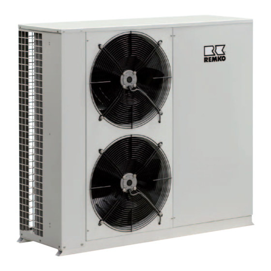
REMKO KWL 130 Operation Manual

REMKO KWL 130 Operation Manual

Air-cooled chiller and air-cooled chiller with heat pump function

Advertisement

REMKO KWL
KWL 130, KWL 160, KWL 180 (INOX), KWL 220 (INOX),
KWL 270 (INOX), KWL 320 (INOX), KWL 370 (INOX)
KWL 130 H, KWL 160 H, KWL 180 H (INOX),
KWL 220 H (INOX), KWL 270 H (INOX), KWL 320 H (INOX),
KWL 370 H (INOX)
Air-cooled Chiller and
Air-cooled Chiller with Heat Pump function
Operation · Technology · Spare parts
Edition GB – B05

Advertisement

Table of Contents
loading

Summary of Contents for REMKO KWL 130

  • Page 1 REMKO KWL KWL 130, KWL 160, KWL 180 (INOX), KWL 220 (INOX), KWL 270 (INOX), KWL 320 (INOX), KWL 370 (INOX) KWL 130 H, KWL 160 H, KWL 180 H (INOX), KWL 220 H (INOX), KWL 270 H (INOX), KWL 320 H (INOX),...
  • Page 3: Table Of Contents

    These instructions are an integral part of the system and must always be kept near or on the device. This operating manual is a translation of the German original. Made by REMKO Subject to modifications; no liability accepted for errors or misprints!
  • Page 4: Safety Notes

    "commissioning ■ and components supplied by hazard-prevention measures report" to REMKO GmbH & Co. KG REMKO is not permitted and when performing installation, at the time when the equipment can cause malfunctions. repair or maintenance work or and that the said documents are cleaning the equipment.
  • Page 5: Transport And Packaging

    Under certain circum- (scroll construction) which stances, it can also be used indoors. increases the pressure and the The unit cooling circuit comprises Construction KWL 130 - KWL 220 Cooling mode Legend: Circulation pump Manual bleeder Plate evaporator Differential pressure switch...
  • Page 6 REMKO KWL (H) Construction KWL 270 - KWL 370 Cooling mode KWL 130 H - KWL 220 H Cooling and heating mode KWL 270 H - KWL 370 H Cooling and heating mode Legend: Circulation pump Manual bleeder Plate evaporator...
  • Page 7: System Configuration

    System configuration The unit is designed as a 2 conduc- System configuration tor system. The system has 2 medium pipes Indoor area 1 Indoor area 2 Indoor area 3 (conductors: supply and return) Condensate drain Condensate drain Condensate drain for cooling using a cold medium Condensate collecting pipe (KWL) or heating using a warm medium (units with HP function...
  • Page 8 REMKO KWL (H) Operating the controller Control panel of the iChiLL controller iChill adaptive The controller has 3 modes: 1. Summer mode (cooling mode) In cooling mode, the warmer me- dium temperature is cooled to the preset, cooler target temperature.
  • Page 9: Key Functions

    Key functions Activate and/or deactivate the unit with the key  /  Key by pressing it for longer than 5 seconds. On the display screen the current display of the the return temperature is shown. min. 5 sec. min. 5 sec. If a potential-free contect is used for the external enabling of the unit, External enabling the controller shows "OFF"...
  • Page 10 REMKO KWL (H) Adaptive cooling and heating function If the programmed target temperature within the system is reached quickly or only a small share of cooling or heating capacity is accepted by the internal equipment, the operating time of the compressor decreases. An op- erating time which is too short can have a negative long-term impact on the operation of the unit.
  • Page 11 Using the SET key, the set value can be displayed during stand-by or Target value input heating mode heating mode for units with HP function. To change the set value, press key for approx. 5 seconds. The display begins to blink. With the keys the value can be adjusted within the limits defined at the factory (St 07 + St 08).
  • Page 12 REMKO KWL (H) Querying the fault reports (See chapter on troubleshooting and customer service) In order to protect the unit from damage, the controller checks the compo- Fault reset nents which are relevant for the safety of the unit by means of sensors for temperature, pressure, configuration, etc.
  • Page 13 Operating structure Standard display > 5 sec. < 2 sec. Param.level 1 without password St 01 Target value cooling St 02 Hysteresis cooling St 03 Target value heating < 2 sec. < 2 sec. > 5 sec. St 04 Hysteresis heating St 09 Output range All open Display target values...
  • Page 14: Care And Maintenance

    • • points. Check fan • • Check refrigerant fill quantity REMKO GmbH & Co. KG or your • • Check condensation drain contractual partner will be pleased • • Test insulation to provide a list of certified firms •...
  • Page 15: Trouble-Shooting And Customer Service

    Trouble-shooting and customer service The unit has been manufactured using state-of-the-art production methods and tested several times to ensure its correct function. If malfunctions should occur, please check the unit as detailed in the list below. For installations with an indoor unit and outdoor unit, observe the chapter "Troubleshooting and customer service" in both operating manuals.
  • Page 16 REMKO KWL (H) Malfunctions Fault Code Possible cause check Remedial measures Does all other electrical Check voltage and if necessary Mains failure equipment function correctly? wait until turned on again. Unit's breaker/mains switch Switch on unit's breaker/ main Is voltage available to the unit?
  • Page 17 Malfunctions Fault Code Possible cause check Remedial measures The unit was configured with HP Have specialist check regulation or ACF1 Configuration error function but without reversing valve. parameters. No configuration of the condenser Have specialist check regulation or ACF2 Configuration error controller.
  • Page 18: Installation Instructions For Qualified Personnel

    REMKO KWL (H) Installation instructions for qualified personnel Important information Lift the unit only at intended In the selection of the ■ ■ before installing lifting points. Never stress the installation site, pay attention medium or refrigerant piping. to the site itself and to any...
  • Page 19 Wall openings Exposure to sunlight further Installation inside buildings increases the temperature of the We recommend that the inside Ensure that heat can dissipate ■ ■ fins and reduces the heat released of the opening be padded or adequately when placing the by the finned heat exchanger.
  • Page 20 1800 1800 All values in mm Minimum clearances KWL 130(H) - 220(H) KWL 270(H) - 320(H) KWL 370 (H)
  • Page 21: Installation

    Transport pallet Remove this before installation. 4. Connect the medium lines. Unit layout Weight loads KWL 130(H) - 160(H) KWL 180(H) - 220(H) KWL 270(H) - 320(H) KWL 370 (H) KWL (H) with medium storage tank 130H...
  • Page 22 If the unit is at first to be oper- ■ KWL 130 (H) - 370 (H) with external medium storage tank (hydr. switch) ated with only a part of the entire system, the medium flow for the missing system compo- nents is to be simulated using a pipe leg regulating valve.
  • Page 23 Minimum/maximum medium flow individual pressure losses of each Medium piping individual unit in the pipeline The chiller`s circulation pump gen- Medium piping can be made of network design must be adjusted erates a constant medium flow; copper, steel or plastic. To minimise to the entire system.
  • Page 24 If a lower anti-freeze protection setting below the possible limits of pa- rameter Ar 01 is necessary, a lower setting can be made after password input. For this purpose, please contact REMKO. The following values must then be input: 0% Ethylene...
  • Page 25: Condensate Draining And Ensured Discharge

    Condensate draining and ensured discharge Fill and drain connection NOTE A connection should be provided Condensate connection Cumulative ice formation in in an area safe from frost for the the lower part of the finned draining of the pipe lines (especial- If the temperature falls below the heated exchanger can develop ly if water is used as a medium).
  • Page 26: Electrical Connection

    REMKO KWL (H) Electrical connection All electrical connections such NOTE CAUTION ■ as network supply, cable remote We recommend the use of safety All electrical installation work control etc. must be carried out fuses. is to be performed by specialty in the unit's switch cabinet.
  • Page 27 (See section "Configuration exter- General fault signal Winter pressure controller nal enabling"). (Standard equipment) (Accessories) This enable is used for example to realise standstill times at night or The connection of a potential free It serves for the expansion of the for the activation/deactivation of general fault signal, for exam- operating range in cooling mode...
  • Page 28: Electrical Components

    REMKO KWL (H) Electrical components Electric components and safety Phase sequence relay Sensor Pb 3 fan controller equipment The phase sequence relay controls The sensor is located on the cool- Pressure switch cooling cycle HP the direction of rotation for the ing circuit's condenser.
  • Page 29: Electrical Circuit Diagram

    Electrical circuit diagram KWL 130(H) - 160(H) Fan controller Compressor Circulation pump Condenser Condenser fan 1 fan 2 KWL 130(H) - 160(H) 2-3 External enabling 4-5 General fault signal 2-6 Cooling-heating switching 9-10 Cable remote control Probe Probe Probe Pressure transducer...
  • Page 30 REMKO KWL (H) KWL 130(H) - 160(H) Anti-freeze heating, cooling medium Reversing valve CW heater (Accessories) (only KWL...H) (Accessories) KWL 180(H) - 320(H) Fan controller Compressor Circulation pump Condenser Condenser fan 1 fan 2...
  • Page 31 KWL 180(H) - 320(H) 2-3 External enabling 4-5 General fault signal 2-6 Cooling-heating switching 9-10 Cable remote control Probe Probe Probe Pressure transducer High Low pres- Diff.press. Intake Outlet LN-contr. pressure reg. pressure sure switch switch (Accessories) switch KWL 180(H) - 320(H) Anti-freeze heating, cooling medium Reversing valve CW heater...
  • Page 32 REMKO KWL (H) KWL 370 (H) Fan controller Compressor Circulation pump Condenser Condenser Condenser Condenser fan 1 fan 2 fan 3 fan 4 KWL 370 (H) 2-3 External enabling 4-5 General fault signal 2-6 Cooling-heating switching Probe Probe Probe Pressure transducer...
  • Page 33 Condenser fan 3 Thermal contact fan 2 B4 not used EV1 Reversing valve Condenser fan 4 FL Differential pressure switch M10 Condenser fan 1 Component equipment KWL 130 KWL 160 KWL 180 KWL 220 KWL 270 KWL 320 KWL 370 KM 1 5.5kW-AC3...
  • Page 34: Leak Testing

    REMKO KWL (H) Before commissioning Leak testing Filling the system If the unit is positioned at the ■ lowest point in the system, the unit preliminary pressure Leak testing is carried out after all The system is filled on-site at the...
  • Page 35: Commissioning

    Commissioning If necessary, change the installa- Function check of the enable ■ ■ NOTE mode / Stand-By (option). tion site. For this, the manufac- Commissioning should only be turer's authorisation is required. Carried out by trained person- Checking the medium cycle nel and after certification to be For cooling and heating sys- ■...
  • Page 36: Unit Dimensions

    Unit dimensions KWL 130(H) - 160(H) KWL 180(H) - 220(H) 1220 1420 Intake Intake Outlet...
  • Page 37: Characteristic Curves

    Characteristic curves Pressure loss KWL 130 (H) KWL 160 (H) KWL 180 (H) KWL 220 (H) KWL 270 (H) KWL 320 (H) KWL 370 (H) Circulation pump KWL 130(H) - 230/400V 0.37/0.5kW 2.5/1.4A 320(H) KWL 370 (H) 230/400V 1.2kW 4.3/2.5A...
  • Page 38 REMKO KWL (H) Equipment pressure, available KWL 130 (H) KWL 160 (H) KWL 180 (H) KWL 220 (H) KWL 270 (H) KWL 320 (H) KWL 370 (H)
  • Page 39: Exploded Views

    Exploded view KWL 130(H) - 220(H) We reserve the right to modify the dimensions and constructional design as part of the ongoing technical development process.
  • Page 40: Spare Parts Lists

    REMKO KWL (H) Spare parts list KWL 180 KWL 220 Designation KWL 180 KWL 220 130 H 160 H Operating panel, compressor element RAL 1110001 1110001 1110002 1110002 1110001 1110001 1110002 1110002 Operating panel, compressor element INOX 1110760 1110760 1110761...
  • Page 41: Exploded Views

    Exploded view KWL 270(H) - 370(H) We reserve the right to modify the dimensions and constructional design as part of the ongoing technical development process.
  • Page 42 REMKO KWL (H) Spare parts list Designation 270 H 320 H 370 H Operating panel, compressor element RAL 1110063 1110063 1110064 1110063 1110063 1110064 Operating panel, compressor element INOX 1110774 1110774 1110775 1110774 1110774 1110775 Condenser protective grid RAL 1110065...
  • Page 43 Cooling capacity KWL 130 (H) KWL 160 (H) KWL 180 (H) KWL 220 (H) Medium outlet Air intake temperature °C [kW] 13,5 13,1 12,3 11,6 16,9 16,1 15,3 14,4 19,0 18,3 17,3 16,5 22,9 22,1 20,8 19,7 13,9 13,4 12,6...
  • Page 44 KWL 130 to 370: Air intake temperature TK 35°C, medium intake 12 °C, medium outlet 7 °C, 0% glycol concentration KWL 130 H to 370 H:Air intake temperature TK 7°C / 85%r.h., medium intake 40 °C, medium outlet 45 °C, 0% glycol concentration...
  • Page 45: Technical Data

    Technical data Series Air-cooled compact chiller with adaptive function Operating mode for cooling Nominal cooling capacity 12,9 15,9 18,1 21,8 27,1 31,5 37,2 Energy efficiency ratio cooling EER 2,42 2,59 2,57 2,56 2,67 2,67 2,65 Setting range return temp. Cooling °C +10 to +18 Operating range - cooling...
  • Page 46 REMKO KWL (H) Technical data Series 130 H 160 H 180 H 220 H 270 H 320 H 370 H Air-cooled compact chiller with heat pump function Operating mode and with the adaptive function for cooling and heating Nominal cooling capacity...
  • Page 47: Ec-Declaration Of Conformity

    Air-cooled water chiller with heat pump function Series / Model: REMKO KWL 130, KWL 160, KWL 180 INOX, KWL 220 INOX KWL 270 INOX, KWL 320 INOX, KWL 370 INOX, KWL 130H, KWL 160H, KWL 180H INOX, KWL 220H INOX, KWL 270H INOX...
  • Page 48 REMKO, a partner helping you find solutions to your problems. Distribution REMKO offers not just a well established sales network both nationally and internationally, but also has exceptionally highly- qualified sales specialists. REMKO field staff are more than...

Table of Contents