
Subscribe to Our Youtube Channel
Related Manuals for REMKO ATY 261 DC


Summary of Contents for REMKO ATY 261 DC
- Page 1 REMKO ATY ATY 261 DC, ATY 351 DC Inverter wall - room air conditioner in split - design Operation · Technology · Spare parts Edition GB – V08...
-
Page 3: Table Of Contents
Read these operating instructions carefully before commissioning / using the device! These instructions are an integral part of the system and must always be kept near or on the device . Made by REMKO Subject to modifications; No liability accepted for errors or misprints! -
Page 4: Safety Notes
■ and components supplied by or maintenance work or complete and return the "certificate REMKO is not permitted and cleaning the equipment. of warranty" and "commissioning can cause malfunctions. report" to REMKO GmbH & The equipment or components Co. -
Page 5: Transport And Packaging
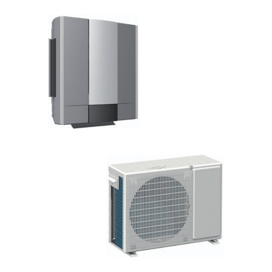
Flow regulator Injection line Equipment description Capillary tube The ATY 261-351 DC room air conditioning units have a REMKO Refrigerant circuit diagram for the indoor unit ATY...AT outdoor component as well as an ATY...IT indoor unit. Vaporiser fan When in cooling mode,... -
Page 6: Operation
REMKO ATY Operation The indoor unit is easily operated using the standard infrared remote control. The indoor unit beeps to acknowledge the correct transmission of data. If it is not possible to program the indoor unit using the remote control, it can also be manually operated. - Page 7 3. Heating mode In this mode, the warm air in the room "MIN."button Buttons on the remote control is warmed to the desired temperature. This button increases the minute value for time and timer 4. Air circulation mode programming. In this mode, the air in the room is recirculated.
-
Page 8: Button Functions
REMKO ATY Button functions A symbol is shown on the display to indicate that the settings are being transferred. ON/OFF Button By pressing the ON / OFF button, you can activate or deactivate your unit. The programmed settings and adjustment values before the unit was turned off will appear on the display. - Page 9 In automatic mode, the controller autonomously selects between heating AUTOMATIC MODE and cooling operation when the unit is first turned on. A nominal temperature of 24 °C is preset. MODE AUTOMATIC In cooling mode, the air in the room is cooled down to the set nominal Cooling MODE temperature.
- Page 10 REMKO ATY Heating MODE In the heating mode, you can heat the room in spring or fall. The desired room temperature is set with buttons / in 1 °C increments. If the room temperature is 1 °C below the selected nominal temperature, then the indoor unit starts to warm up the air in the room.
- Page 11 In dehumidification mode, the room temperature cannot be set. Due to the low temperature of the refrigerant, the dew point of the air at the Dehumidification MODE condenser is undercut. The excess moisture in the air is condensed on the condenser, the room is dehumidified.
- Page 12 REMKO ATY The oscillating function of the air discharge fins can be adjusted with this SWING Button (covered) butto. This makes it possible to switch directly between a fixed position and the oscillating function. The air distribution in the room is improved using the swing function.
- Page 13 The controller turns the unit on after programming. During operation, PROGRAMMINGTIMER ON all settings can be seen on the display. Out of operation, only the timer settings are visible. Timer on 30 sec. HR/MIN The controller turns the unit off after programming. During operation, PROGRAMMING TIMER OFF all settings can be seen on the display.
-
Page 14: Operation
REMKO ATY By pressing the "ION" button several times, the "ION" function, INDOOR UNIT DISPLAY the "Turbo" function, or both can be set at the same time. Ion function TURBO The unit is equipped with an ion generator to generate negative ions. -
Page 15: Shutdown
1. Disconnect the supply voltage outdoor unit with plastic to to the equipment. REMKO GmbH & Co. KG or your avoid infiltration of dirt into contractual partner will be pleased the unit. 2. Clean the unit with a soft damp to provide a list of certified firms cloth. - Page 16 REMKO ATY 1. Switch the indoor unit via the remote control to air circulation (the front cover of the air inlet Type of task must be open!) (Figure 2). Checks/ Maintenance/Inspections 2. Open the lower display cover on the front side of the unit •...
-
Page 17: Troubleshooting And Customer Service
Troubleshooting and customer service The equipment and components are manufactured using state-of-the-art production methods and tested several times to verify their correct function. If malfunctions should occur, please check the functions as detailed in the list below. Please inform your dealer if the unit is still not working correctly after all the functional checks have been performed! Fault Fault Possible cause... - Page 18 REMKO ATY Problem display by blinker code LED in AT Display Fault description Checks Remedial measures yellow green Air circulation sensor on ER01 flashes indoor unit is defective / Check resistance (see p. 19) Replace defective sensor triggered Indoor unit power supply...
-
Page 19: Control And Resistance
Controller, safety controller and resistance Hot gas sensor, IPM AT sensor AT condenser sensor, AT ambient temperature sensor IT vaporiser sensor, IT circulation sensor Temp. Resistance Resistance Temp. 160.73 kΩ 27.42 kΩ 125.57 kΩ 22.15kΩ 98.78 kΩ 18.00 kΩ 78.23 kΩ 14.72 kΩ... -
Page 20: Installation Instructions For Qualified Personnel
REMKO ATY Installation instructions for qualified personnel Important notes prior to devices with intensive thermal Only use the union nuts for the ■ installation radiation. Installation near refrigerant pipes included in the sources of thermal radiation delivery, and remove them only reduces the output of the unit. - Page 21 Wall openings Selection of the installation location Wind A wall opening of at least The indoor unit is designed for If the unit is being installed in ■ 70 mm diameter and 10 mm horizontal wall installation in the windy areas, ensure that the slope from the inside to the upper wall area (at least 1.75 warm outlet air discharges in the...
- Page 22 Air intake 1000 and repair work and facilitate optimum air distribution. 1000 discharge 1000 ATY 261 DC AT ATY 351 DC AT 100 mm 100 mm 700 mm 700 mm 400 mm 400 mm 100 mm...
-
Page 23: Installation
Installation Oil return measures NOTE Open display cover Installation may only be If the outdoor unit is installed at performed by authorised a higher level than the indoor unit, specialists. we recommend that suitable oil return measures are taken. Usually an oil pump bend is installed for every 2.5 metres of height difference. - Page 24 REMKO ATY 4. Lay the refrigerant lines from 13. Now fully tighten the fittings Connecting the the indoor unit to the outdoor using 2 suitably sized open- refrigerant lines component. Ensure that the ended spanners. fastenings are adequate and if...
-
Page 25: Monitoring For Leaks
Monitoring for leaks Deburring the refrigerant line Once all the connections have The time required to generate been established, the pressure the vacuum is dependent on Refrigerant line gauge station is attached as the pipework volume of the follows to the Schrader valve indoor unit and the length of the (if fitted): refrigerant lines. -
Page 26: Condensate Drain
REMKO ATY Condensate drain Electrical connection Due to the dew point shortfall The condensation hose is designed Mains cable must be installed as on the vaporiser, condensation is to be installed on the right and the voltage supply to the indoor unit created on the indoor unit during left side (view from front). -
Page 27: Electrical Connection Diagram
3. Connect the unit to the mains cable and control cable on the Electrical connection diagram outdoor component. (See electrical connection ATY 261 DC / ATY 351 DC diagram). Outdoor component the indoor unit Mains cable Exterior conductor 4. Re-assemble the unit. -
Page 28: Electrical Circuit Diagram
REMKO ATY Electrical circuit diagram Check the refrigerant lines and ■ ATY 261 DC AT / ATY 351 DC AT insulation for damage. Check the electrical connection Test ■ Air-intake sensor between the indoor unit and Condenser sensor the outdoor unit for correct... -
Page 29: Commissioning
Commissioning Function test of Cooling 9. Check the correct function operating mode of the condensation line by NOTE pouring distilled water into the Commissioning is only to be 1. Remove the caps condensation tray. performed and documented from the valves. A bottle with a spout is by specially trained personnel. -
Page 30: Unit Dimensions
REMKO ATY Unit dimensions ATY 261 DC AT / ATY 351 DC AT All values in mm ATY 261 DC IT / ATY 351 DC IT All values in mm We reserve the right to modify the dimensions and constructional design as part of the ongoing technical development process. -
Page 31: Technical Data
1/4 (6,35) (mm) Coolant connection - suction line Inches 3/8 (9,52) 1/2 (12,7) (mm) ATY 261 DC IT ATY 351 DC IT Data specific to indoor unit Operating range °C/ %r.F +16 to +32 / 80% +16 to +32 / 80% Adjustment range - Cooling °C... -
Page 32: Exploded View
REMKO ATY Exploded view ATY 261 DC IT / ATY 351 DC IT We reserve the right to modify the dimensions and constructional design as part of the ongoing technical development process. Spare parts list Designation ATY 261 DC IT... - Page 33 Exploded view ATY 261 DC AT / ATY 351 DC AT We reserve the right to modify the dimensions and constructional design as part of the ongoing technical development process. Spare parts list Designation ATY 261 DC AT ATY 351 DC AT...
-
Page 34: Declaration Of Conformity
REMKO ATY... - Page 35 Notes...
- Page 36 SFlb Customer service Our equipment operates precisely and reliably. However, in the event of a fault, REMKO REMKO GmbH & Co. KG Hotline customer service is quickly at the scene. Our comprehensive Air conditioning and heating technology...
Need help?
Do you have a question about the ATY 261 DC and is the answer not in the manual?
Questions and answers