Table of Contents
Advertisement
Quick Links
Advertisement
Table of Contents

Related Manuals for IFM CR2011


Summary of Contents for IFM CR2011
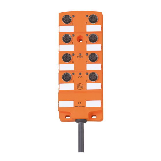
- Page 1 Device manual Output module CR2011...
-
Page 2: Table Of Contents
Output Module CR2011 Contents 1 Preliminary note � � � � � � � � � � � � � � � � � � � � � � � � � � � � � � � � � � � � � � � � � � � � � � � � � 3 2 Safety instructions �... -
Page 3: Preliminary Note
It is not permitted and leads to an exclusion of any liability and warranty claims� 3 Function and features The CR2011 output module enables decentralised triggering of actuators and pro- portional valves� The coil current can be monitored and controlled via the integra- ted current measurement�... -
Page 4: Function
Output Module CR2011 4 Function ● The module supports binary and analog outputs and is therefore classified in the device profile "I/O module" to CiA DS 401� ● As regards the output function the module can be configured� The module supports 5 operating modes: - binary outputs with current detection, up to 2�5 A... -
Page 5: Dimensions And Mounting
Output Module CR2011 5 Dimensions and mounting M12x1 28,5 ► Use suitable washers� Tightening torque of the fixing screws: max� 1�8 Nm 6 Electrical connection To protect the whole system (wiring and output module) the individual elec- tric circuits must be protected with max� 16A�... -
Page 6: 6�3 Outputs With Current Monitoring
Output Module CR2011 6.3 Outputs with current monitoring M12 connector PIN connection switching output L+ 2 (measuring resistor integrated) external voltage - n�c� 7 Operating indicators LED colour Status Description no supply voltage module in the stand-by mode CANopen state: PREOPERATIONAL / PREPARED... -
Page 7: Set-Up
Output Module CR2011 8 Set-up 8.1 PLC configuration in CODESYS 2.3 Parameter setting of the device functions and of the CAN interface is directly done from the application programmed with CODESYS 2�3� To do so, the "Electronic Data Sheet" (EDS) is integrated via the CODESYS PLC configuration�... -
Page 8: 8�2 Plc Configuration In Codesys 3�5
Output Module CR2011 8.2 PLC configuration in CODESYS 3.5 The "Electronic Data Sheet“ (EDS) is installed in the [Device Repository]� Proceed as follows in the main menu: ► Click on [Tools] / [Device Repository]� ► Select [Fieldbuses] / [CiA CANopen] / [CiA Remote Device] and click on [In- stall]�... -
Page 9: 8�2�2 Syncmonitoring
8.3 Electronic Data Sheet The EDS contains the description of all parameters and I/O data of the device in a format defined by CANopen� The EDS files are provided for all CANopen slaves by ifm electronic� The EDS files are available at www�ifm�com�... -
Page 10: Parameter Setting
Output Module CR2011 9 Parameter setting With the function "restore" (, index 1011) the parameters (except the baud rate and the node ID) can be assigned to the factory default values� With the next power on they become valid� 9.1 Parameter list... -
Page 11: Technical Data
Output Module CR2011 10 Technical data Housing 8-channel splitter box made of polyamide (PA) with integrated electronics, fully potted Dimensions 152x 60 x 22 mm (L x W x H) Device connection PUR/PVC cable 2 m, 2 x 1�5mm² (operating voltage) / 3 x 0�5mm² (CAN interface) -
Page 12: 10�1�2 Pwm Outputs
Output Module CR2011 10.1.2 PWM outputs With the configuration as PWM output two outputs each are combined� The output signal is present at one of the two outputs while the other output is OFF (left/right function, up/ down function)� It is possible to immediately switch over from one output to the other�... -
Page 13: Object Directory
Output Module CR2011 11 Object directory 11.1 Manufacturer Specific Profile Area; index 2000 to 5FFF Index S-Idx Designation Type Default Description Number of the entries 2000 u8, ro 0x04 Configuration = number of the output channels configuration channel pair 1/2 *) - Page 14 Output Module CR2011 Index S-Idx Designation Type Default Description Setting of the 0x20 The node ID used to access the output module in 20F0 u8, rw Node ID (= 32) the CANopen network� Setting of the 0x20 The node ID used to access the output module in...
-
Page 15: 11�2 Communication Profile Area; Index 1000 To 1Fff
Output Module CR2011 11.2 Communication Profile Area; index 1000 to 1FFF Index S-Idx Designation Type Default Description 1000 Device Type u32, ro 0xF0191 Profile 401; outputs, binary and analog Bit-coded to profile 301, the following is supported: 0b 0000 0000 no error... - Page 16 Output Module CR2011 Index S-Idx Designation Type Default Description Number of 1010 u8, ro 0x01 Number of the "save" options save options "save all All parameters are automatically saved after a 1010 u32, rw 0x02 parameters” change� Number of 1011...
- Page 17 Output Module CR2011 Index S-Idx Designation Type Default Description Mapping Rec Number of the application objects linked with 1600 u32, ro 0x01 PDO 1 the binary output PDO 6200 Sldx 01 contains 1 byte (binary outputs) 0b 0000 0001 = Out 1...
-
Page 18: Fault Correction
Output Module CR2011 Index S-Idx Designation Type Default Description Idx 2002 01 contains the actual current value 0x2002 01 channel 1/2 Idx 2002 02 contains the actual current value 0x2002 02 Index in channel 3/4 1A00 the object u32, rw... -
Page 19: Maintenance, Repair And Disposal
The disposal must be carried out according to the corresponding national environ- mental regulations� 14 Declaration of conformity The CE Declaration of Conformity is available at: www�ifm�com 15 Terms and abbreviations 0b ��� binary value (for bit coding), e�g� 0b0001 0000 0d ���... - Page 20 Output Module CR2011 "CAN in Automation e�V�" (user and manufacturer organisation in Germany /Erlangen) Definition and control body for CAN and CAN-based network protocols CiA DS Draft Standard (published CiA specification which usually has not been modified or supple- mented for one year)
- Page 21 Output Module CR2011 Process Data Object; in the CANopen network for transfer of process data in real time; such as the speed of a motor PDOs have a higher priority than SDOs; in contrast to the SDOs they are transferred without confirmation� PDOs consist of a CAN message with identifier and up to 8 bytes of user data�...
Need help?
Do you have a question about the CR2011 and is the answer not in the manual?
Questions and answers