
Subscribe to Our Youtube Channel
Related Manuals for IFM ECOMAT 100 CR1500


Summary of Contents for IFM ECOMAT 100 CR1500
- Page 1 Geräte-Handbuch Device manual CAN Tastaturmodul CPM 100 CAN key pad module CPM 100 CR1500...
-
Page 2: Table Of Contents
CPM 100 CAN TASTATURMODUL Sicherheitshinweise Diese Beschreibung ist Bestandteil des Gerätes. Sie enthält Texte und Abbildungen zum korrekten Umgang mit dem Modul und muss vor einer Installation oder dem Einsatz gelesen werden. Befolgen Sie die Angaben der Dokumentation. Nichtbeachten der Hinweise, Verwendung außerhalb der nachstehend genannten bestimmungsgemäßen Verwendung, falsche Installation oder Handhabung können Beeinträchtigun- gen der Sicherheit von Menschen und Anlagen zur Folge haben. -
Page 3: Bestimmungsgemäße Verwendung / Funktion
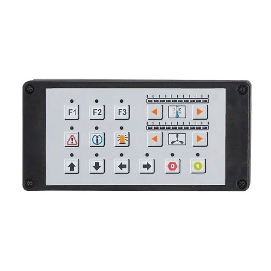
CPM 100 CAN TASTATURMODUL Bestimmungsgemäße Verwendung / Funktion Das Tastatur- und Anzeigemodul CR1500 für CANopen Netzwerke kann als Auf- oder Einbaugerät in Führerstände, Bedienkonsolen oder Schaltschränken einge- setzt werden. Die Auswertung und Parametrierung der Tasten und LEDs erfolgt gemäß IEC 61131-3 innerhalb des Steuerungsprogramms. Funktionsbibliotheken für das Programmiersystem CoDeSys unterstützen die Ein- bindung der Tastaturfunktionen in das Applikationsprogramm. -
Page 4: Technische Daten
CPM 100 CAN TASTATURMODUL Technische Daten Betriebsspannung 10...30 V DC; SELV Stromaufnahme 200 mA (24 V DC) (Die Stromaufnahme im Fehlerfall muss durch geeignete Maßnahmen auf 1 A begrenzt werden) Funktionstasten 12, über Anwenderprogramm auswertbar Bedientasten 4 Pfeiltasten, über Anwenderprogramm auswertbar Tastenbeschriftung 3 wechselbare Einschubstreifen Status-LEDs... -
Page 5: Maße
CPM 100 CAN TASTATURMODUL Tastenbeschriftung Die applikationsspezifische Beschriftung der Funktionsstasten und LED-Ketten erfolgt über Einsschubstreifen. Diese Streifen können mit einem PC und einem beliebigen Text- oder Grafikprogramm erstellt und ausgedruckt werden. Um das Einschieben der Streifen zu vereinfachen, sollte der Ausdruck vorzugswei- se auf stärkerem Papier erfolgen. -
Page 6: Montage Und Elektrischer Anschluss
CPM 100 CAN TASTATURMODUL Montage und elektrischer Anschluss Das Modul darf nur von einer Elektrofachkraft eingebaut, angeschlossen und in Betrieb gesetzt werden. Das Tastaturmodul enthält C-MOS-Bauelemente die durch elektrostatische Entladung beschädigt werden können. Berühren Sie deshalb vor dem Öff- nen des Moduls ein geerdetes Teil. Gehäuseoberteil Kontaktstifte Gehäuseunterteil... - Page 7 CPM 100 CAN TASTATURMODUL Schaltschrank- bzw. Bedienpultmontage (Einbau) 1. Bereiten Sie mit Hilfe der beiliegenden Montageschablone (#5310674) einen Ausschnitt mit 4 Bohrungen in der Fronttafel des Schaltschrankes oder des Bedienpultes vor. 2. Lösen Sie die 4 Schrauben des Tastaturmoduls und heben Sie das Gehäuse- oberteil vom Gehäuseunterteil ab.
-
Page 8: Tasten- Und Led-Betriebsarten
CPM 100 CAN TASTATURMODUL Tasten- und LED-Betriebsarten Zählweise der Tasten und LEDs LED-Kette 1 und Pfeiltasten oben links/rechts LED-Kette 2 und Pfeiltasten unten links/rechts Tasten Jede der 12 Funktions- und 4 Pfeiltasten ermöglicht folgende Betriebsarten: • Taster-Betrieb (Tasten-Bit ist TRUE solange Taste gedrückt wird) •... - Page 9 CPM 100 CAN TASTATURMODUL Status-LEDs Jede Status-LED kann individuell angesteuert werden. Der LED-Anzeigemodus wird nicht über SDO parametriert, sondern kann direkt per Receive PDO aus der Applikation angesteuert werden. Die ersten 3 Byte des Rec PDOs beinhalten den LED-Status. 4 Betriebszustände stehen zur Verfügung: •...
-
Page 10: Parameter- Und Emcy-Objekt-Übersicht
CPM 100 CAN TASTATURMODUL Parameter- und EMCY-Objekt-Übersicht Über die Funktion „Restore“ (s. Objektverzeichnis, Idx 1011) können die Parame- ter (Ausnahme Baudrate und Node-ID) mit den werkseitig hinterlegten Default- Werten belegt werden. Diese sind dann nach dem nächsten Einschalten der Ver- sorgungsspannung gültig. -
Page 11: Wartung, Instandsetzung Und Entsorgung
CPM 100 CAN TASTATURMODUL EMCY Objekte Folgende Fehlercodes gemäß DSP-401 bzw. DSP-301 werden unterstützt: EMCY Error Zusatz Beschreibung Code Code 0x6100 0x11 0x00 „Internal Software“ Überlauf einer Rx-Queue; Frequenz der Rx PDOs zu groß. Reset nur extern, über Eintrag in Idx 1003 00 0x6101 0x11 0x00... -
Page 12: Herstellerspezifische Profile; Index 2000 Bis 5Fff
CPM 100 CAN TASTATURMODUL Objektverzeichnis Herstellerspezifische Profile; Index 2000 bis 5FFF Index S-Idx Name Default Beschreibung 2000 0x00 Konfiguration u8, ro 0x10 Anzahl der Einträge (= Anzahl der Tasten = 16) Tastenbetriebsart 0x01 Taste 1 u8, rw 0x00 0 = Taster-Betriebsart 1 = Toggle-Betriebsart 0x0A Taste 10... - Page 13 CPM 100 CAN TASTATURMODUL Objektverzeichnis Herstellerspezifische Profile; Index 2000 bis 5FFF Index S-Idx Name Default Beschreibung 2003 0x00 Umschlagpunkt u8, ro 0x02 Anzahl der eingebundenen LED-Ketten für Farbwechsel 0x01 Umschlagpunkt u8, rw 0x01 Farbumschlagpunkt LED-Kette 1 Farbwechsel Wertebereich 1...10 (0x00...0A) LED-Kette 1 (Werte <...
-
Page 14: Kommunikationsprofile; Index 1000 Bis 1Fff
CPM 100 CAN TASTATURMODUL Objektverzeichnis Kommunikationsprofile; Index 1000 bis 1FFF Index S-Idx Name Default Beschreibung 1000 0x00 device type u32, ro 0x0000 herstellerspezifisch 1001 0x00 error register u8, ro 0x00 Bitcodiert gemäß Prof 301; unterstützt wird: 0b 0000 0000 kein Fehler 0b x00x 0001 generic error 0b x001 000x communication error... - Page 15 CPM 100 CAN TASTATURMODUL Objektverzeichnis Kommunikationsprofile ; Index 1000 bis 1FFF Index S-Idx Name Default Beschreibung 1014 0x00 COB-ID u32, rw - Modul reagiert nicht auf 0x40000080 EMCY +Node ID fremde EMCY Mess. (Bit 31 = 0) - Modul generiert EMCY Mess. (Bit 30 = 1) - 11 Bit ID (Bit 29 = 0) - ID = 0x80 + Node ID...
- Page 16 CPM 100 CAN TASTATURMODUL Objektverzeichnis Kommunikationsprofile; Index 1000 bis 1FFF Index S-Idx Name Default Beschreibung 1600 0x00 Mapping u32, rw 0x03 Anzahl der eingebundenen Receive PDO Applikations-Objekte zur Ansteuerung der Status-LEDs und der LED-Ketten 0x01 PDO mapping u32, rw im Idx 6200 01 stehen 3 Byte LED-Stati, 0x6200 01 for the 1st Ansteuerung erfolgt über jeweils 2 Bit,...
- Page 17 CPM 100 CAN TASTATURMODUL Objektverzeichnis Kommunikationsprofile; Index 1000 bis 1FFF Index S-Idx Name Default Beschreibung 1800 0x00 Transmit PDO u8, ro 0x05 Anzahl der Einträge Trans PDO; binär Eingänge (Tasten-Status) Funktions- Pfeiltasten- Status 0x01 COB-ID u32, rw 0x180 + - PDO ist gültig (Bit 31 = 0) Trans PDO Node ID - CAN-ID des Trans PDOs...
-
Page 18: Programmierung
CPM 100 CAN TASTATURMODUL Programmierung Allgemeines Das Tastaturmodul muss als CANopen-Slave mit den CANopen-Startfunktionen „COP_MSTR_BOOTUP“ und „COP_MSTR_MAIN“ vom R 360-Master initialisiert und in den Zustand „OPERATIONAL“ versetzt werden (Status-LEDs blinken 5 x). Programmier-Funktion Wird die Funktion „CR1500“ in das Programm eingebunden, sorgt diese auto- matisch für eine ständige Aktualisierung der Tasten- und LED-Stati in der Steue- rung. - Page 19 – deklariert werden. Für Konfigurationsdaten kann im Deklarationsteil bereits eine Wertzuweisung enthalten sein. Im Programmablauf kann der Zugriff auf eine Strukturkomponente z.B. wie dar- gestellt erfolgen. Screenshot Programmieroberfläche Weitere CoDeSys Programmierbeispiele für das Tastaturmodul erhalten Sie auf Nachfrage von der ifm electronic gmbh. EITE...
- Page 20 CPM 100 CAN TASTATURMODUL Funktion: CR1500 CR1500 Library: CR1500_C.lib ENABLE CFG_RESULT INIT IO_RCV Zweck: Parametriert und liest NODE_ID die Konfigurations- und E/A-Daten CFG_READ des Tastaturmoduls CFG_WRITE CR1500 CFG_DATA RX_TYPE TX_TYPE SYNC IO_DATA Parameter Name Datentyp Beschreibung Eingänge ENABLE BOOL TRUE: Funktion wird abgearbeitet INIT BOOL...
- Page 21 CPM 100 CAN TASTATURMODUL Datenstruktur: TYPE CR1500 ConfigStruct CR1500 ConfigStruct STRUCT GUARDTIME: TIME; Zweck: LIFETIME: BYTE; Parameter- und Konfigurationsdaten Key1: BOOL; können geschrieben oder gelesen werden. Key2: BOOL; Key3: BOOL; Die Datenstruktur wird dem Funktions- Key4: BOOL; eingang „CFG_DATA“ über den ADR- Key5: BOOL;...
- Page 22 CPM 100 CAN TASTATURMODUL Datenstruktur: TYPE CR1500 InOutStruct CR1500 InOutStruct STRUCT Key1_Direct: BOOL; (BinIn) Zweck: Key1_Delay: BOOL; (BinIn) Aktuelle E/A-Daten werden gelesen bzw. geschrieben. Key12_Delay: BOOL; (BinIn) KeyLeft1_Direct: BOOL; (BinIn) Die Datenstruktur wird dem KeyLeft1_Delay: BOOL; (BinIn) Funktionseingang „IO_DATA“ KeyRight1_Direct: BOOL; (BinIn) über den ADR-Operator KeyRight1_Delay: BOOL;...
- Page 23 CPM 100 CAN TASTATURMODUL Strukturkomponenten (Pfeiltasten) Name Datentyp Taste Bit-Status im ... Taster-Betrieb Toggle-Betrieb Byte Bit KeyLeft1_Direct BOOL Taste TRUE, wenn gedrückt (nicht unterstützt) KeyLeft1_Delay BOOL o. links TRUE, nach Ablauf d. Zeit KeyRight1_Direct BOOL Taste TRUE wenn gedrückt (nicht unterstützt) KeyRight1_Delay BOOL o.
-
Page 24: Begriffe Und Abkürzungen
CPM 100 CAN TASTATURMODUL Begriffe und Abkürzungen 0b ... binärer Zahlenwert (zur Bitcodierung), z.B. 0b0001 0000 0x ... hexadezimaler Zahlenwert, z.B. 0x64 (= 100 dezimal) Baudrate Übertragungsgeschwindigkeit (1 Baud = 1 Bit/sec.) CAN Application Layer CAN basierendes Netzwerkprotkoll auf Applikationsebene Controller Area Network (Bussystem für den Einsatz im Mobilbereich) CAN_H CAN-High;... - Page 25 CPM 100 CAN TASTATURMODUL Node Guarding Parametrierbare zyklische Überwachung von Slave-Netzwerkteilnehmern durch einen übergeordneten Master-Knoten, sowie die Überwachung dieses Abfragemechanismus durch die Slave-Teilnehmer. Node-ID Knotenpunkt-Identifier (Kennung eines Teilnehmers im CANopen Netz) Objekt (auch OBJ) Oberbegriff für austauschbare Daten/Botschaften innerhalb des CANopen- Netzwerks Objektverzeichnis enthält alle CANopen-Kommunikationsparameter eines Gerätes, sowie gerä-...
- Page 26 CPM 100 CAN KEYPAD MODULE Safety instructions These instructions are part of the unit. They contain text and fig- ures about the correct handling of the module and must be read before installation or use of the unit. Adhere to the information in the documentation. Non-observance of the instructions, operation which is not in accordance with use as prescribed below, wrong installation or handling can affect the safety of people and the plant.
-
Page 27: Function And Features
CPM 100 CAN KEYPAD MODULE Function and features The keypad and display module CR1500 for CANopen systems can be mounted on or in driver's cabs, control panels or control cabinets. The evaluation and para- meter settings of the keys and LEDs are made according to IEC 61131-3 within the controller software. -
Page 28: Technical Data
CPM 100 CAN KEYPAD MODULE Technical data Operating voltage 10...30 V DC; SELV Current consumption 200 mA (24 V DC) (The current consumption in the case of an error must be limited to 1 A by appropriate measures) Function keys 12, to be evaluated via application program Operating keys 4 arrow keys, to be evaluated via application program... -
Page 29: Dimensions
CPM 100 CAN KEYPAD MODULE Key labelling The application-specific labelling of the function keys and rows of LEDs is made by inserted strips. These strips can be labelled by means of any text or graphic software on a PC and can then be printed out. To simplify the insertion of the strips thicker paper should be used for the print- out. -
Page 30: Mounting And Electrical Connection
CPM 100 CAN KEYPAD MODULE Mounting and electrical connection The module must be installed, connected and put into operation by a qual- ified electrician. The keypad module contains C-MOS elements which can be damaged by electrostatic discharge. Touch a grounded part before opening the module. Gehäuseoberteil module upper part Kontaktstifte... - Page 31 CPM 100 CAN KEYPAD MODULE Mounting in a control cabinet or operating panel 1. Prepare a cutout with 4 holes in the front panel of the control cabinet or the operating panel by means of the enclosed mounting template (#5310674). 2.
-
Page 32: Key And Led Operating Modes
CPM 100 CAN KEYPAD MODULE Key and LED operating modes Numbering of the keys and LEDs LED-Kette 1 row of LEDs 1 und Pfeiltasten and upper arrow oben links/rechts keys left/right LED-Kette 2 row of LEDs 2 und Pfeiltasten and lower arrow unten links/rechts keys left/right Keys... - Page 33 CPM 100 CAN KEYPAD MODULE Status LEDs Each status LED can be triggered individually. The parameters of the LED display mode are not set via SDO but can be triggered directly by Receive PDO from the application. The first 3 bytes of the Rec PDO contain the LED status. 4 operating states are available: •...
-
Page 34: List Of Parameters And Emcy Objects
CPM 100 CAN KEYPAD MODULE List of parameters and EMCY objects With the function "Restore" (see object directory, Idx 1011) the factory default values can be restored (except for the parameters "Baud rate" and the "Node ID"). With the next power on they become valid. List of parameters Index Default value... -
Page 35: Maintenance, Repair And Disposal
CPM 100 CAN KEYPAD MODULE EMCY objects The following error codes according to DSP-401 or DSP-301 are supported: EMCY Error Additional Description code code 0x6100 0x11 0x00 "Internal Software" Overflow of an Rx queue; frequency of the Rx PDOs is too high. Only external reset, via an entry in Idx 1003 00. -
Page 36: Manufacturer-Specific Profiles, Index 2000 To 5Fff
CPM 100 CAN KEYPAD MODULE Object directory Manufacturer-specific profiles, index 2000 to 5FFF Index S-Idx Name Type Default Description 2000 0x00 Configuration of u8, ro 0x10 Number of entries the push button (= number of keys = 16) operating mode 0x01 key 1 u8, rw... - Page 37 CPM 100 CAN KEYPAD MODULE Object directory Manufacturer-specific profiles, index 2000 to 5FFF Index S-Idx Name Type Default Description 2003 0x00 colour change u8, ro 0x02 number of integrated rows of LEDs point 0x01 colour change u8, rw 0x01 colour change point row of LEDs 1 point value range 1...10 (0x00...0A) row of LEDs 1...
-
Page 38: Communication Profiles; Index 1000 To 1Fff
CPM 100 CAN KEYPAD MODULE Object directory Communication profiles; index 1000 to 1FFF Index S-Idx Name Type Default Description 1000 0x00 device type u32, ro 0x0000 manufacturer-specific 1001 0x00 error register u8, ro 0x00 bit coded according to profile 301; the following is supported: 0b 0000 0000 no error 0b x00x 0001 generic error... - Page 39 CPM 100 CAN KEYPAD MODULE Object directory Communication profiles; index 1000 to 1FFF Index S-Idx Name Type Default Description 1014 0x00 COB-ID u32, rw - The module does not react 0x40000080 EMCY +Node ID on foreign EMCY mess. (bit 31 = 0) - Module generates EMCY message (bit 30 = 1) - 11 Bit ID (bit 29 = 0)
- Page 40 CPM 100 CAN KEYPAD MODULE Object directory Communication profiles; index 1000 to 1FFF Index S-Idx Name Type Default Description 1600 0x00 Mapping u32, rw 0x03 number of integrated application Receive PDO objects for triggering of the status LEDs and the rows of LEDs. 0x01 PDO mapping u32, rw...
- Page 41 CPM 100 CAN KEYPAD MODULE Object directory Communication profiles; index 1000 to 1FFF Index S-Idx Name Type Default Description 1800 0x00 Transmit PDO u8, ro 0x05 number of entries Trans PDO; binary inputs (key status) function arrow key status 0x01 COB-ID u32, rw 0x180 +...
-
Page 42: Programming
If the function "CR1500" is integrated into the program, this automatically ensu- res a continuous updating of the key and LED states in the controller. The func- tion "CR1500" can be found in the library "CR1500_C.lib" of the ifm program- ming software CoDeSys. - Page 43 For configuration data the declaration part can already contain an assignment of values. In the program access to a structure component can be represented as follows: Screenshot of the programming platform More CoDeSys programming examples of the keypad module can be obtained from ifm electronic gmbh on request. PAGE...
- Page 44 CPM 100 CAN KEYPAD MODULE Function: CR1500 CR1500 Library: CR1500_C.lib ENABLE CFG_RESULT INIT IO_RCV Purpose: Sets the parameters and reads NODE_ID the configuration and I/O data CFG_READ of the keypad module CFG_WRITE CR1500 CFG_DATA RX_TYPE TX_TYPE SYNC IO_DATA Parameter Name Data type Description Inputs...
- Page 45 CPM 100 CAN KEYPAD MODULE Data structure: TYPE CR1500 ConfigStruct CR1500 ConfigStruct STRUCT GUARDTIME: TIME; Purpose: LIFETIME: BYTE; Parameter and configuration data Key1: BOOL; can be written or read. Key2: BOOL; Key3: BOOL; The data structure is assigned Key4: BOOL; to the function input "CFG_DATA"...
- Page 46 CPM 100 CAN KEYPAD MODULE Data structure: TYPE CR1500 InOutStruct CR1500 InOutStruct STRUCT Key1_Direct: BOOL; (BinIn) Purpose: Key1_Delay: BOOL; (BinIn) Current I/O data are read or written. Key12_Delay: BOOL; (BinIn) KeyLeft1_Direct: BOOL; (BinIn) The data structure KeyLeft1_Delay: BOOL; (BinIn) is assigned to the KeyRight1_Direct: BOOL;...
- Page 47 CPM 100 CAN KEYPAD MODULE Structure components (arrow keys) Name Data Bit status in ... type push button operation toggle operation Byte Bit KeyLeft1_Direct BOOL arrow key TRUE if pressed (not supported) KeyLeft1_Delay BOOL upper left TRUE when delay time has elapsed KeyRight1_Direct BOOL arrow key...
-
Page 48: Terms And Abbreviations
CPM 100 CAN KEYPAD MODULE Terms and abbreviations 0b ... binary value (for bit coding), e.g. 0b0001 0000 0x ... hexadecimal value, e.g. 0x64 (= 100 decimal) Baudrate transmission speed (1 baud = 1 bit/s) CAN Application Layer CAN-based network protocol on application level Controller Area Network (bus system for use in mobile applications) CAN_H CAN-High;... - Page 49 CPM 100 CAN KEYPAD MODULE Node ID node identifier (identification of a participant in the CANopen network) Object (also OBJ) term for data/messages which can be exchanged in the CANopen network Object directory contains all CANopen communication parameters of a device as well as device-specific parameters and data Access to the individual entries is possible via the index and S index.
Need help?
Do you have a question about the ECOMAT 100 CR1500 and is the answer not in the manual?
Questions and answers