Table of Contents
Advertisement
Quick Links
Advertisement
Table of Contents

Related Manuals for IFM CR2012


Summary of Contents for IFM CR2012
- Page 1 Device manual CabinetModule Input/output module CR2012...
-
Page 2: Table Of Contents
CabinetModule CR2012 Contents 1 Preliminary note � � � � � � � � � � � � � � � � � � � � � � � � � � � � � � � � � � � � � � � � � � � � � � � � � 3 1�1 Symbols used�... -
Page 3: Preliminary Note
CabinetModule CR2012 1 Preliminary note Technische Daten, Zulassungen, Zubehör und weitere Informationen unter www�ifm�com� 1.1 Symbols used ► Instruction > Reaction, result […] Designation of keys, buttons or indications → Cross-reference Important note Non-compliance may result in malfunction or interference�... -
Page 4: Functions And Features
SELV voltage of which is not grounded� The terminals may only be supplied with the signals indicated in the technical data or on the unit label and only the approved accessories of ifm electronic gmbh may be connected�... -
Page 5: Mounting
CabinetModule CR2012 ● There are 1 server SDO and 4 default PDOs according to CiA DS 401�The PDO mapping can be changed (dynamic PDO mapping)� The default identifiers are assigned according to the “predefined connection set”� ● The COB IDs of the PDOs as well as the transmission type (synch/asynch) of the individual PDOs can be configured�... -
Page 6: 4�2 Fixing
CabinetModule CR2012 4.2 Fixing ► Fix the device using 2 M4 x L screws via transversely arranged bore holes� Tighten the screws alternately crosswise� – Tightening torque: 1�5 Nm – Mounting position: as required – Hole dimensions: (→ 8.1 Dimensions, mechanics, electronics) 4.3 Cooling... -
Page 7: Electrical Connection
Pin connection (→ 8.4 Wiring) You can find more information about the available connector accessories at: www�ifm�com → Data sheet direct → CR2012 → Accessories 5.2 Fuses ► To protect the whole system (wiring and device) the individual electric circuits... -
Page 8: Set-Up
CabinetModule CR2012 6 Set-up 6.1 PLC configuration in CODESYS 2.3 Parameter setting of the device functions and of the CAN interface is directly done from the application programmed with CODESYS 2�3� To do so, the „Electronic Data Sheet“ (EDS) is integrated via the CODESYS PLC configuration�... -
Page 9: 6�2 Plc Configuration In Codesys 3�5
CabinetModule CR2012 6.2 PLC configuration in CODESYS 3.5 The „Electronic Data Sheet“ (EDS) is installed in the [Device Repository]� Proceed as follows in the main menu: ► Click on [Tools] / [Device Repository]� ► Select [Fieldbuses] / [CiA CANopen] / [CiA Remote Device] and click on [In- stall]�... -
Page 10: 6�2�2 Syncmonitoring
6.3 Electronic Data Sheet The EDS contains the description of all parameters and I/O data of the device in a format defined by CANopen� The EDS files are provided for all CANopen slaves by ifm electronic� The EDS files are available at www�ifm�com�... -
Page 11: Parameter Setting
CabinetModule CR2012 7 Parameter setting 7.1 Automatic saving Automatic saving of the communication and device parameters can be activated or deactivated by means of the “save parameter” entry (object directory, index 1010, S-Idx 01)� ● Value 0x00: There is no automatic saving� Changed parameters are only valid until the device is switched off or until the next reset�... -
Page 12: 7�3 Communication Profiles; Idx 1000 To 1Fff
CabinetModule CR2012 7.3 Communication profiles; Idx 1000 to 1FFF Parameters Index in Default value (factory Change saved Change object preset) automatically effective directory COB ID Synch Object 1005 00 0x80 adjustable after PreOp Communication Cycle 1006 00 0x00 (Off) adjustable... -
Page 13: 7�4 Manufacturer-Specific Profiles; Idx 2000 To 6Fff
CabinetModule CR2012 7.4 Manufacturer-specific profiles; Idx 2000 to 6FFF Parameters Index in object Default value Change saved Change directory (factory preset) automatically effective Config� channel 1 2000 01 0x01 (Bin IN) Config� channel 2 2000 02 0x01 (Bin IN) Config� channel 3... -
Page 14: 7�5 Emcy Objects
CabinetModule CR2012 7.5 EMCY objects The following error codes are supported according to DSP-301 and DSP-401: EMCY code Error reg Additional Description code 0x6100 0x11 0x00 "Internal Software": overflow of an Rx queue; e�g� frequency of the Rx PDOs too high... -
Page 15: Technical Data
Plug set for CabinetModules, wirable, consisting of: AMP crimp housing, 1 x 6 poles, 2x18 poles incl. crimp contacts (Junior Power Timer) ifm electronic gmbh • Friedrichstraße 1 • 45128 Essen We reserve the right to make technical alterations without prior notice! CR2012 / page 1... -
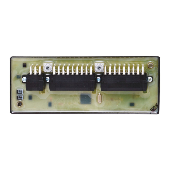
Page 16: 8�2 Connecting, Operating And Display Elements
PWM preset value < 1% measuring range binary output switched (ON) analogue output: PWM preset value > 2% measuring range ifm electronic gmbh • Friedrichstraße 1 • 45128 Essen We reserve the right to make technical alterations without prior notice! CR2012 / page 2 25.04.2013... -
Page 17: 8�3 Characteristics Of The Inputs/Outputs, Test Standards And Regulations
EN 50155 clause 12.2 mechanical/climatic tests EN 50121-3-2 EMC noise emission and noise immunity additional information on request ifm electronic gmbh • Friedrichstraße 1 • 45128 Essen We reserve the right to make technical alterations without prior notice! CR2012 / page 3 25.04.2013... -
Page 18: 8�4 Wiring
16 Bin IN 16 – Bin OUT 16 PWM 16 Plug X3 CAN_L CAN_H ifm electronic gmbh • Friedrichstraße 1 • 45128 Essen We reserve the right to make technical alterations without prior notice! CR2012 / page 4 25.04.2013... -
Page 19: Maintenance, Repair And Disposal
► Dispose of the device in accordance with the national environmental regula- tions� 10 Approvals/standards Test standards and regulations (→ 8 Technical data) The CE Declaration of Conformity and the E1 approval are available at: www�ifm�com → Data sheet direct → CR2012 → Approvals... -
Page 20: Anhang / Appendix
CabinetModule CR2012 11 Anhang / Appendix Objektverzeichnis / Object directory 11.1 Communication profiles; Idx 1000 to 1FFF Index S-Idx Name Type Default Description 1000 device type 0x000F0191 I/O-module profile DS401 digital/analogue inputs/outputs 1001 error register 0x00 1003 pre-definded error field... - Page 21 CabinetModule CR2012 Index S-Idx Name Type Default Description 1014 COB ID EMCY 0x40000080 module generates EMCY + NodeID messages (bit 30 = 1) 1016 number of monitored 0x01 devices consumer heartbeat 0x00000000 heartbeat monitoring time for time node n monitoring of only one node is...
- Page 22 CabinetModule CR2012 Index S-Idx Name Type Default Description 5th mapping object 0x00000000 no object Rec PDO 1 6th mapping object 0x00000000 no object Rec PDO 1 7th mapping object 0x00000000 no object Rec PDO 1 8th mapping object 0x00000000 no object...
- Page 23 CabinetModule CR2012 Index S-Idx Name Type Default Description COB ID Transmit 0x00000280 PDO is valid (bit 31 = 0) PDO 2 + NodeID transmission type 0x01 0x01���0xF0 = synch cyclic Trans PDO 2 0xFE���0xFF = asynch (immediately) inhibit timer Trans 0x0000 min�...
- Page 24 CabinetModule CR2012 Index S-Idx Name Type Default Description 6th mapping object 0x00000000 no object Trans PDO 2 7th mapping object 0x00000000 no object Trans PDO 2 8th mapping object 0x00000000 no object Trans PDO 2...
-
Page 25: 11�2 Manufacturer-Specific Profiles; Idx 2000 To 6Fff
CabinetModule CR2012 11.2 Manufacturer-specific profiles; Idx 2000 to 6FFF Index S-Idx Name Type Default Description 2000 number of IOs 0x10 configuration channel 0x01 0x00 = off 0x01 = binary input configuration channel 0x01 0x00 = off 0x01 = binary input... - Page 26 CabinetModule CR2012 Index S-Idx Name Type Default Description configuration channel 0x03 0x00 = off 0x01 = binary input 0x03 = analog input absolute (voltage 0���10 V; 0x00���0xFF) 0x06 = analog input ratiometric configuration channel 0x02 0x00 = off 0x01 = binary input...
- Page 27 CabinetModule CR2012 Index S-Idx Name Type Default Description 8bit user variable 3 8bit user variable 4 8bit user variable 5 8bit user variable 6 8bit user variable 7 8bit user variable 8 8bit user variable 9 8bit user variable 10...
- Page 28 CabinetModule CR2012 Index S-Idx Name Type Default Description user string 2 16 characters 6100 number of binary 0x01 inputs (16bit) binary inputs bits 0���15: binary inputs channel 1����16 6200 number of binary 0x01 outputs (8bit) binary outputs 0x00 0b0000 0001 = channel 7...
Need help?
Do you have a question about the CR2012 and is the answer not in the manual?
Questions and answers