
Related Manuals for ZIEHL-ABEGG AMblue


Summary of Contents for ZIEHL-ABEGG AMblue
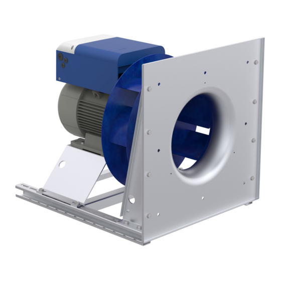
- Page 1 AMblue Fan with asynchronous motor and mounted frequency inverter Assembly instructions Keep for reference! L-BAL-F069-GB 1735 Index 004 Part.-No. 00703523-GB...
-
Page 2: Table Of Contents
Assembly instructions AMblue Content General notes ............. - Page 3 Assembly instructions AMblue 5.12 Status output “OC” (Open-Collector) ........
-
Page 4: General Notes
We do not accept any liability for possible errors or omissions in the information contained in data, illustrations or drawings provided. ZIEHL-ABEGG SE is not liable for damage due to misuse, incorrect use, improper use or as a consequence of unauthorized repairs or modifications. -
Page 5: Explanations Of Symbols
Assembly instructions AMblue Safety instructions • Conveyance of abrasive or adhesive media. • Conveyance of liquid media. • Use of the fan and add-on parts (e.g. safety grille) as a resting surface or climbing aid. • Fans are not designed for walking on even with an additive diffusor attachment (retrofit kit)! Do not climb onto fans without suitable aids. -
Page 6: Modifications / Interventions In The Device
Use only genuine spare parts / genuine wearing parts / genuine accessories from ZIEHL-ABEGG.Th- ese parts were specifically designed for the device. There is no guarantee that parts from non-original sources are designed and manufactured in correspondence with load and safety requirements. -
Page 7: Employment Of External Personnel
In order to achieve this, the device protects itself by active temperature management. Note on the ErP directive ZIEHL-ABEGG SE wishes to point out that, based on the directive (EU) no. 327/2011 of the Commis- sion of 30th of March 2011 for enforcing directive 2009/125/EC (hereinafter referred to as ErP directive), the operational area of certain fans within the EU is bound by certain prerequisites. -
Page 8: Disposal / Recycling
Assembly instructions AMblue Mounting • Transport the fan(s) either in the original packaging or, in the case of larger fans, on the dedicated transportation fixtures. – Depending on the type: Lifting eyes, bore holes in the housing flange, motor bed, fastening brackets and support plates, bore holes in the motor housing for screwing in eye bolts •... -
Page 9: Permissible Position Of The Mounted Frequency Inverter
Assembly instructions AMblue Mounting • Prior to installing the fan, it is to be checked whether the safety zone as per EN ISO 13857 and in household appliances as per EN 60335 are met. If the installation height (danger zone) above the... - Page 10 (Spring or damping elements are not usually parts of the standard scope of supply). The assignment of the spacing dimensions of the damping elements can be taken from the catalogues on our home page under www.ziehl-abegg.de in the section Download - Ventilation and Control Engineering.
-
Page 11: Optimal Installation Distances According To For Rh
Assembly instructions AMblue Mounting Optimal installation distances according to for RH../ ER../ GR.. fans • Distance on suction side: LA ≥ 0.5 x DSa * • Distance on the pressure side: LD ≥ 1 x DSa • Impeller blade external-diameter : Ø DSa •... -
Page 12: Electrical Installation
Assembly instructions AMblue Electrical installation " Insert cables properly and ensure tightness of the cable glands. " Attach the cover of terminal compartment again carefully after connection ( Electrical Installa- tion). Cable inlet 1 FSDM12/17: M16, FSDM25/32/39/46: M20 2 FSDM12/17: M25, FSDM25/32: M32, FSDM39/46: M40... -
Page 13: Terminal Compartment
“TB” must be reinserted on mo- tors with thermostats. In devices of the AMblue and PMblue series fully assembled by ZIEHL-ABEGG, the plug “TB” / “TP” is already in the correct position on delivery. -
Page 14: Mains Connection
Assembly instructions AMblue Electrical installation This equipment complies with IEC 61000-3-12 provided that the short-circuit power S is greater than or equal to R at the interface point between the user's supply and the public system. It is the responsibility of the installer or user of the equipment to ensure, by consultation with the distribution... -
Page 15: Motor Protection
Assembly instructions AMblue Electrical installation Motor protection Motor protection is provided by the temperature sensors installed in the motor “ TP” (PTC). When a connected temperature sensor responds or there is an interruption between the two terminals “TB/TP” the device switches off and does not switch back on. - Page 16 Assembly instructions AMblue Electrical installation 0...100 %PWM (factory setting) Control via external setting signal PWM D1 GND 10V D1 GND 10V 24V (10 V) E1.1 E1.1 10 k f = 1...10 kHz 13.06.2014 i_jumper_motor_mounted_pwm.eps 15...28 V 0...20 mA Control via external setting signal 0...20 mA D1 GND E1.1...
-
Page 17: Output Voltage "10 V
Assembly instructions AMblue Electrical installation Diagram setting signal and motor speed 100 % n-min 20 % n-max. = 100 % n-min 40 % n-max. = 90 % n-min 0 % n-max. = 100 % Analog In 1 0...10 V 90 100 0...100 % PWM 0...20 mA... -
Page 18: Relay Outputs "K1
Assembly instructions AMblue Electrical installation Danger due to electric current • No disconnection (no potential isolation in accordance with VBG4 §6) in remote control of the device! • Never apply line voltage to the digital input! 5.11 Relay outputs “K1”... -
Page 19: Option Add-On Modules
This enables fast and simple commissioning and energetically and acoustically optimal operation of the fan. With PMblue and AMblue fans the ZAstick is already in the slot provided in the terminal compartment of the inverter upon delivery. I.e. these products... -
Page 20: Function
Information This installation procedure already takes place prior to delivery for PMblue and AMblue fans. The stick can then be left in the slot or removed at any time. However, it is recommended to leave it plugged into the device to avoid losing it. -
Page 21: Description
Motor Setup or Add- on module). 5. Fans from ZIEHL-ABEGG SE are delivered balanced in accordance with DIN ISO 21940-11 for the appropriate fan category in accordance with ISO 14694. Check the fan for mechanical vibrations after installation. If the limit values of the corresponding fan category are exceeded in start-up, you must have the motor/impeller unit checked by an expert and rebalanced if necessary before continuous operation is permitted. -
Page 22: Diagnostics / Faults
Assembly instructions AMblue Diagnostics / Faults 8 Diagnostics / Faults Trouble shooting Type of error Possible cause Adjustment Fan does not run No line voltage Check line voltage (anymore) Line failure Under - or overvoltage Earth fault Check motor connection and line voltage... -
Page 23: Status Out With Flash Code
Assembly instructions AMblue Diagnostics / Faults Status Out with flash code Operating conditions are indicated by the status LED with flashing code. 23.04.2012 v_flash_explain_1_x.VSD Reaction of device Relay Code Explanation Adjustment In the event of a mains interruption the unit switches “OFF” and automatically de-energized, 13 - “ON”... - Page 24 Assembly instructions AMblue Diagnostics / Faults Reaction of device Relay Code Explanation Adjustment Phase failure / line error Following a shutoff, a startup attempt is made after approximately 15 s, if the The controller is provided with a built-in voltage supply is high enough. This...
-
Page 25: Service Work
Assembly instructions AMblue Service work Reaction of device Relay Code Explanation Adjustment Line voltage too low The modulation is switched off immedi- Line voltage below a fixed limit for longer ately at undervoltage, error message after 75 s. than 75 s. -
Page 26: Cleaning
• Repair, e.g. by welding is prohibited! • Bolted-on wheels and/or wings may only be replaced by authorised ZIEHL-ABEGG SE staff. The manufacturer shall not be liable for damage caused through improper repair work. • The fan or motor is maintenance-free due to the use of ball bearings with “life-time lubrication”. At the end of the grease service life (see Technical Data), it is necessary to change the bearing. -
Page 27: Enclosure
Assembly instructions AMblue Enclosure 10 Enclosure 10.1 Technical data Line voltage* 3 ~ 380...480 V, 50/60 Hz rating plate) Maximal line fuse** 5.5 kW (FSDM12): 16 A 7.5 kW (FSDM17): 20 A 11 kW (FSDM25): 35 A 15 kW (FSDM32): 35 A 18.5 kW (FSDM39): 50 A... - Page 28 Assembly instructions AMblue Enclosure 11/15/18.5/22 kW (FSDM25/32/39/46) Conductor cross section single-wire: 16 mm Conductor cross-section fine-wire: 16 mm , with wire end ferrule 10 mm Conductor (AWG): 6 dB(A) values product catalog Ball bearings grease service-life (F ) during standard usage ca. 30 - 40,000 h...
-
Page 29: Connection Diagram
Assembly instructions AMblue Enclosure 10.2 Connection diagram AMblue PMIcontrol Basic-M FSDM... 0...20 mA 3 ~ Motor mit eingebauten Temperaturfühlern with internal thermistors 0...10 V/PWM Kontaktbelastung Contact rating max. AC 250 V 2 A GND 10V 24V E1,1 Service parameter load... -
Page 30: Ec Declaration Of Incorporation
Assembly instructions AMblue EC Declaration of Incorporation EC Declaration of Incorporation ZA87-GB-1712 Index 006 10.3 00296702-GB as defined by the EC Machinery Directive 2006/42/EC, Annex II B The design of the incomplete machine: • Axial fan FA.., FB.., FC.., FE.., FF.., FS.., FT.., FH.., FL.., FN.., FV.., DN.., VR.., VN.., ZC.., ZF.., ZN.. -
Page 31: Index
Assembly instructions AMblue Index 10.4 Index modulation motor protection 13, 15 add-onmodule motor speed analog inputs Assembly asynchronous motor one-quadrant drives overload 24-25 Ball bearings Bearing parameter memory cable glands changing the bearing Checksum confirmation number rating plate 21, 26... -
Page 32: Manufacturer Reference
Assembly instructions AMblue Index 10.5 Manufacturer reference Our products are manufactured in accordance with the relevant international regulations. If you have any questions concerning the use of our products or plan special uses, please contact: ZIEHL-ABEGG SE Heinz-Ziehl-Straße 74653 Künzelsau...
Need help?
Do you have a question about the AMblue and is the answer not in the manual?
Questions and answers