Sign In
Upload
Manuals
Brands
MICRO-EPSILON Manuals
Measuring Instruments
confocalDT 2451
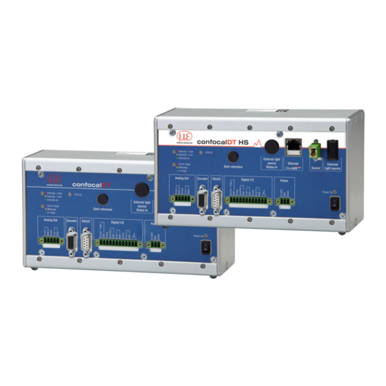
MICRO-EPSILON confocalDT 2451 Manuals
Manuals and User Guides for MICRO-EPSILON confocalDT 2451. We have
1
MICRO-EPSILON confocalDT 2451 manual available for free PDF download: Operating Instructions Manual
MICRO-EPSILON confocalDT 2451 Operating Instructions Manual (166 pages)
Brand:
MICRO-EPSILON
| Category:
Measuring Instruments
| Size: 24 MB
Table of Contents
Table of Contents
3
1 Safety
7
Symbols Used
7
Warnings
7
Notes on CE Marking
8
Intended Use
8
Proper Environment
8
2 Functional Principle, Technical Data
9
Short Description
9
Measuring Principle
9
Glossary
10
Operating Modes
10
Sensors
10
Technical Data
11
3 Delivery
16
Unpacking, Included in Delivery
16
Storage
16
4 Assembly
16
Controller
16
External Light Source IFX2471
17
Controller Operating Elements
17
Controller Leds
18
Electrical Controller Connections
19
Handling of Pluggable Screw Terminals
19
Supply Voltage (Power)
19
Rs422
19
Ethernet, Ethercat
19
Analog Output
20
Switching Outputs (Digital I/O)
20
Synchronization (Inputs/Outputs)
21
Encoder Inputs
23
Status Inputs for External Light Sources
23
Sensor Cable, Optical Fiber
24
Sensors
26
Dimensions IFS2402 Sensors
26
Dimensions IFS2403 Sensors
27
Dimensions IFS2404 Sensors
28
Dimensions IFS2405 Sensors
29
Dimensions IFS2406 Sensors
30
Dimensions IFS2407 Sensors
31
Start of Measuring Range
32
Mounting an Installation Bracket
33
General
33
IFS2402 Sensors
33
IFS2403 Sensors
33
IFS2405 and IFS2406 Sensors
34
IFS2404 and IFS2407 Sensors
35
5 Operation
36
Commissioning
36
Operation Using Ethernet
36
Requirements
36
Access Via Ethernet
37
Measured Value Presentation with Ethernet
38
User Interface, Basic Preferences
39
Introduction
39
Measurement Program
39
Material Database
40
Selecting a Sensor
40
Exposure Mode / Measuring Rate
41
Video Signal
43
Dark Reference
45
Measurements and Web
46
Distance Measurements
46
Thickness Measurement of Transparent Objects
48
Load / Save Settings in the Controller
50
Saving Settings in the Controller
51
Loading from the Controller
51
6 Advanced Settings
52
Login, Switching User Level
52
Detection Threshold
52
Averaging, Error Handling, Spike Correction, Statistics
53
Notes on Averaging
53
Video Averaging
54
Measurement Averaging
54
Error Handling (Hold Last Value)
56
Spike Correction
56
Statistics
57
Zeroing, Mastering
58
Digital Interfaces
59
Selecting a Digital Interface
59
RS422 Interface
59
Ethernet
60
Ethercat
60
Switching Outputs
61
Assignment of the Switch Outputs (Digital I/O)
61
Limit Value Settings
61
Switch Threshold of the Error Outputs
61
Analog Output
62
Output Data Rate
62
Encoder Inputs
63
Interpolation
63
Effect on the Reference Track
63
Set on Value
63
Maximum Value
64
Trigger Mode
64
Triggering the Measured Value Recording
65
Triggering the Measurement Value Output
65
Trigger Time Difference
65
Synchronization
66
Manage Setups on PC
66
Extras
67
Masking the Evaluation Range
67
Light Source Reference
68
Help/Info
68
Edit Material Data Bank
69
Create Known Material
69
Create Unknown Material
69
Different Peak Selection in the Thickness Measurement Program
71
Timing, Measurement Value Flux
72
7 Errors, Repairs
73
Troubleshooting
73
Web Interface Communication
73
Distance Measurements
73
Thickness Measurements
73
Changing the Sensor Cable for IFS2405 and IFS2406 Sensors
73
Changing the Protective Glass for IFS2405 and IFS2406 Sensors
74
Ifs2405/Ifs2406
74
Ifs2406/90-2.5
74
8 Software Update
75
9 Software Support with Medaqlib
75
10 Software Support with IFD2451/2461/2471 Tool
76
System Requirements
76
Cable and Program Routine Requirements
76
Measurement
76
11 Liability for Material Defects
77
12 Service, Repair
77
13 Decommissioning, Disposal
77
Appendix
78
A 1 Accessories, Services
78
Factory Settings
80
Xenon Light Source IFX2471
80
Warnings
80
A 3.2 Functionality
80
A 3.3 Unpacking, Items Included in Delivery, Accessories and Installation
81
A 3.4 Tips for Operation
82
Technical Data
82
A 3.6 Operating Elements
83
Changing the Xenon Lamp Module
84
Change Fuses
85
Troubleshooting
85
A 4 Multilayer Measurement, Controller Ifc24X1Mp
86
A 4.1 User Interface
86
A 4.1.1 General, Settings / Measuring Program
86
A 4.1.2 Video Signal for Multilayer Measurements
87
Measurements (Measurement Values Versus Time Diagram)
88
A 4.2 LED Meaning for Multilayer Measurements
90
A 4.3 Digital Interfaces / Data Selection
90
A 4.3.1 Switching Outputs / Limit Values
91
A 4.3.2 Analog Output
91
A 5 ASCII Communication with Controller
92
A 5.1 General
92
A 5.2 Commands Overview
92
A 5.3 General Commands
95
A 5.3.1 General
95
A 5.3.1.1 Help
95
A 5.3.1.2 Controller Information
95
A 5.3.1.3 Reply Type
95
A 5.3.1.4 Parameter Overview
95
A 5.3.1.5 Synchronization
96
A 5.3.1.6 Booting the Sensor
96
A 5.3.1.7 Querying the Controller Temperature
96
A 5.3.2 User Level
96
A 5.3.2.1 Changing the User Level
96
A 5.3.2.2 Changing to User Level
96
A 5.3.2.3 Querying the User Level
96
A 5.3.2.4 Defining a Standard User
96
A 5.3.2.5 Changing the Password
97
Sensor
97
A 5.3.3.1 Info about Calibration Tables
97
A 5.3.3.2 Sensor Number
97
A 5.3.3.3 Sensor Information
97
A 5.3.3.4 Dark Correction
97
A 5.3.3.5 Warning Threshold in the Event of Contamination
97
A 5.3.3.6 Light Correction
98
A 5.3.4 Trigger Modes
98
A 5.3.4.1 Trigger Type
98
A 5.3.4.2 Effect of the Trigger Input
98
A 5.3.4.3 Trigger Level
98
A 5.3.4.4 Number of Output Measurement Values
98
A 5.3.4.5 Software Trigger Pulse
99
A 5.3.4.6 Settings Encoder Triggering
99
A 5.3.5 Encoder
99
A 5.3.5.1 Encoder Interpolation Depth
99
A 5.3.5.2 Effect of the Reference Track
99
A 5.3.5.3 Encoder Value
99
A 5.3.5.4 Setting Encoder Value Per Software
99
A 5.3.5.5 Reset the Detection of the First Marker Position
100
A 5.3.5.6 Maximum Encoder Value
100
Interfaces
100
A 5.3.6.1 Ethernet IP Settings
100
A 5.3.6.2 Setting for Ethernet Measured Value Transfering
100
A 5.3.6.3 Setting RS422 Baud Rate
100
A 5.3.6.4 Change Ethernet / Ethercat
100
A 5.3.7 Parameter Management, Load / Save Settings
101
A 5.3.7.1 Save Parameter
101
A 5.3.7.2 Load Parameter
101
A 5.3.7.3 Default Settings
101
A 5.4 Measurements
101
A 5.4.1 General
101
A 5.4.1.1 Measurement Mode
101
A 5.4.1.2 Peak Selection
101
A 5.4.1.3 Exposure Mode
102
A 5.4.1.4 Measuring Rate
102
A 5.4.1.5 Exposure Time
102
A 5.4.1.6 Apply Exposure Time
102
A 5.4.1.7 Video Signal Request
102
A 5.4.2 Video Signal
102
A 5.4.2.1 Reduction of Region of Interest
102
A 5.4.2.2 Video Averaging
102
A 5.4.2.3 Peak Detection Threshold
103
Material Data Base
103
A 5.4.3.1 Material Table
103
A 5.4.3.2 Select Material
103
A 5.4.3.3 Display Material Properties
103
A 5.4.3.4 Edit Material Table
103
A 5.4.3.5 Delete a Material
104
A 5.4.4 Number of Peaks, Material Settings Multilayer Measurements
104
A 5.4.4.1 Number of Peaks and Enabling/Disabling Refractive Correction
104
A 5.4.4.2 Material Settings
104
Measurement Value Processing
104
A 5.4.5.1 Averaging of Measurement Value
104
A 5.4.5.2 Spike Correction
104
A 5.4.5.3 Selection of the Signal for the Statistics, Multilayer Measurement
104
A 5.4.5.4 Setting the Statistics Calculation
104
A 5.4.5.5 Reset the Statistics Calculation
105
A 5.4.5.6 Selection of the Signal for the Mastering / Zero Setting, Multilayer Measurement
105
A 5.4.5.7 Setting Masters / Zero
105
A 5.5 Data Output
105
A 5.5.1 General
105
A 5.5.1.1 Selection Digital Output
105
A 5.5.1.2 Output Data Rate
105
A 5.5.1.3 Error Processing
105
A 5.5.2 Select Measurement Values to be Output
106
A 5.5.2.1 Data Selection Displacement Measurement for RS422 / Ethernet
106
A 5.5.2.2 Data Selection Thickness Measurement for RS422 / Ethernet
106
A 5.5.2.3 Data Selection Statistic Values for RS422 and Ethernet
107
A 5.5.2.4 Data Selection Optional Values for RS422 and Ethernet
107
A 5.5.2.5 Switching on Output of Non Linearized Distances
107
A 5.5.2.6 Set Video Output
108
Switching Outputs
108
A 5.5.3.1 Error Switching Outputs
108
A 5.5.3.2 Limit Values
108
A 5.5.3.3 Switching Level
109
A 5.5.4 Analog Output
109
A 5.5.4.1 Data Selection
109
A 5.5.4.2 Output Range
109
A 5.5.4.3 Two-Point Scaling
109
A 5.6 Measured Value Format
110
A 5.6.1 Video Signal
110
A 5.6.2 Exposure Time
111
A 5.6.3 Measuring Rate
111
A 5.6.4 Encoder
111
A 5.6.5 Measured Value Counter
111
A 5.6.6 Time Stamp
112
A 5.6.7 Measurement Data (Displacements and Intensities)
112
A 5.6.8 Trigger Time Difference
112
A 5.6.9 Error Status
113
A 5.6.10 Differences (Thicknesses)
114
A 5.6.11 Statistic Values
114
A 5.7 Measurement Data Format
114
A 5.7.1 Data Format RS422 Interface
114
A 5.7.2 Measurement Data Transmission to a Measurement Value Server Via Ethernet
115
A 5.7.2.1 Description Flags1
116
A 5.7.2.2 Description Flags2
116
A 5.7.2.3 Error Codes Ethernet Interface
117
A 5.7.3 Ethernet Video Signal Transmission
117
A 5.8 Warning and Error Messages
118
Ethercat Documentation
121
Preamble
121
Structure of Ethercat®-Frames
121
Ethercat® Services
121
A 6.1.3 Addressing and Fmmus
122
A 6.1.4 Sync Manager
122
A 6.1.5 Ethercat State Machine
123
A 6.1.6 Canopen over Ethercat
123
A 6.1.7 Process Data PDO Mapping
123
A 6.1.8 Service Data SDO Service
124
A 6.2 Coe - Object Directory
125
A 6.2.1 Communication Specific Standard Objects (Cia DS-301)
125
A 6.2.2 Manufacturer Specific Objects
128
Error Codes for SDO Services
145
A 6.4 Measurement Data Formats
146
A 6.4.1 Measured Values
146
A 6.4.2 Video Signal
146
A 6.4.2.1 Video Signal Output Via Service Data Object
146
A 6.4.2.2 Video Signal Output Via Process Data
148
A 6.5 Distributed Clock
152
A 6.5.1 Introduction
152
A 6.5.2 Synchronization
152
A 6.5.3 Synchronization off
152
A 6.5.4 Slave
152
A 6.5.5 Apply Selected Settings
152
A 6.5.6 Setting Regardless of Twincat
152
A 6.6 Oversampling
153
A 6.7 Meaning of STATUS-LED in Ethercat Operation
157
A 6.8 Ethercat Configuration with the Beckhoff Twincat© Manager
158
Operating Menu
162
Advertisement
Advertisement
Related Products
MICRO-EPSILON confocalDT 2461
MICRO-EPSILON scanCONTROL 25 BL Series
MICRO-EPSILON scanCONTROL 2500/BL
MICRO-EPSILON scanCONTROL 2510/BL
MICRO-EPSILON scanCONTROL 2910
MICRO-EPSILON scanCONTROL 2960BL
MICRO-EPSILON optoCONTROL 2700
MICRO-EPSILON confocalDT IFD2410 Series
MICRO-EPSILON confocalDT IFD2411 Series
MICRO-EPSILON confocalDT IFD2415 Series
MICRO-EPSILON Categories
Measuring Instruments
Accessories
Industrial Equipment
Controller
Security Sensors
More MICRO-EPSILON Manuals
Login
Sign In
OR
Sign in with Facebook
Sign in with Google
Upload manual
Upload from disk
Upload from URL