Durr Dental CAS 1 Installation And Operating Instructions Manual
Combi-separator
Hide thumbs
Also See for CAS 1:
- Installation and operating instructions manual (36 pages) ,
- Nstallation and operating instructions (52 pages)

Related Manuals for Durr Dental CAS 1


Summary of Contents for Durr Dental CAS 1
- Page 1 CAS 1 Combi-Separator Installation and operating instructions 7117100018L30 *7117100018L30*...
- Page 3 Technical data ....CAS 1 Combi-Separator ..Type plate ....
-
Page 4: Table Of Contents
16 Transporting the unit ....16.1 Close CAS 1 ....Appendix 17 Handover record .... - Page 5 These installation and operating instructions apply to: Refer to Operating Instructions. CAS 1 REF: 7117-100-51 Wear protective gloves. Warnings and symbols Warnings Disconnect all power from the unit.
- Page 6 The Installation and Operating Instructions must Intended purpose not be copied or reprinted, neither in full nor in The CAS 1 Combi-Separator is designed for part, without written authorisation from Dürr Den- continuous separation of liquids and air and for tal.
- Page 7 Important information – Use for separation of dust, sludge, plaster or Installation and repairs similar. Installation, readjustments, alterations, ❯ – Use in conjunction with flammable or explosive upgrades and repairs must be carried out by mixtures. Dürr Dental or by qualified personnel specifi- cally approved and authorized by Dürr Dental.
- Page 8 Important information Uncontaminated parts (e.g. electronics, plastic ❯ NOTICE and metal parts etc.) should be disposed of in accordance with the local waste disposal regu- Erroneous operation mode due to use lations. immediately adjacent to other devices or with other stacked devices If you have any questions about the correct ❯...
- Page 9 Service kit (3-year interval) ..7117-980-32 CAS 1 ..... . 7117-100-51 Service kit (5-year interval) ..7117-980-30 –...
- Page 10 Product description Technical data CAS 1 Combi-Separator Electrical data – centrifuge motor Rated voltage 24 AC Frequency 50 / 60 Rated power Current consumption in stand-by Signal input from hose manifold 24 AC 50/60 Signal output 24 DC Media £ 350...
- Page 11 Product description Ambient conditions during operation Temperature °C +10 to +40 Relative humidity < 70 Classification Medical Device Class Electromagnetic compatibility (EMC) Interference emission measurements High-frequency emissions in accordance with CISPR 11 Group 1 Class B Interference voltage at the power supply connection Compliant CISPR 11:2009+A1:2010 Electromagnetic interference radiation...
- Page 12 Product description Electromagnetic compatibility (EMC) Interference immunity measurements Immunity to voltage dips, short interruptions and voltage variations Compliant IEC 61000-4-11:2004 Immunity to interference levels, near fields of wireless HF communication devices Radio service Frequency band Test level TETRA 400 380 - 390 GMRS 460 430 - 470 FRS 460...
- Page 13 Product description Electromagnetic compatibility (EMC) Interference immunity measurements on the supply input Immunity to conducted disturbances, induced by radio- frequency fields – AC mains voltage IEC 61000-4-6:2013 0.15–80 MHz Compliant ISM frequency bands 0.15–80 MHz 80% AM at 1 kHz Immunity to voltage dips, short interruptions and voltage variations Compliant...
- Page 14 Product description Type plate The type plates are located on the cover of the motor. Type plate Evaluation of conformity This device has been subjected to conformity acceptance testing in accordance with the cur- rent relevant European Union guidelines. This equipment conforms to all relevant requirements.
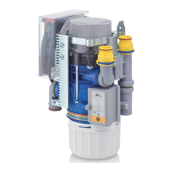
- Page 15 Product description Operation CAS 1 Fluid intake Vacuum, to suction unit Aspiration input Fluid output Motor Separation Separation rotor Centrifuge Light barriers (3x) Sensor enclosure Cone pump Amalgam collector vessel Float sensor Fluids Amalgam particles 7117100018L30 2011V003...
- Page 16 Separation In various types, a station selection valve is At the inlet connection (3) of the CAS 1, the aspi- already integrated in the CAS 1. The station rated fluid/air mix is accelerated and set into a selection valve is on the connection (2) of the spiral motion in the separation unit (6).
- Page 17 Product description off brakes the motor, as a result of which the ring of water, which continues to rotate due to inertia, rinses the separated particles out of the centri- fuge (8) downwards into the collector vessel. The separated amalgam particles form a sedi- ment in the replaceable collector vessel.
- Page 18 Setup options Install an all-pole disconnect switch with a con- ❯ CAS 1 Combi-Separator tact opening width of at least 3 mm in the elec- – Directly in the treatment unit. trical connection to the mains power supply.
- Page 19 Installation of the CAS 1 in treatment units The CAS 1 Combi Separator for KaVo treatment units must be set up in a defined installation setup in order to meet the relevant safety stand- ards.
- Page 20 Station selection valve In various types, the station selection valve is Spittoon connections directly mounted on the CAS 1. The station In some dental units it is possible that noises can selection valve (for separate installation) should be heard at the spittoon, which are amplified by be fitted in the suction pipe in the treatment unit, the funnel shape of the spittoon itself.
- Page 21 X3.1 Place selection valve / safety valve (only If the installation of the amalgam separator in a CAS 1, max. output 8 W) neighbouring room or in the basement results in X3.2 Rinsing unit (CAS 1 only) distances of more than 3 m, we recommend...
- Page 22 Assembly Commissioning In many countries technical medical prod- ucts and electrical devices are subject to regular checks at set intervals. The owner must be instructed accordingly. Turn on the unit power switch or the main sur- ❯ gery switch. Carry out an electrical safety check in accord- ❯...
- Page 23 Assembly Service program 7117100018L30 2011V003...
- Page 24 Assembly Every time the service key is pressed, the sedi- 10 Description of the service ment level is checked. If a test collector vessel is used for this, the different levels can be scanned program and made visible on the display panel. While changing the collectors (collector vessel - Wear protective equipment to avoid any test collector vessel ) in the service program the...
-
Page 25: Amalgam Collector Vessel Not In Position
Usage 11.3 Amalgam collector vessel is Usage 100% full Yellow LED is on 11 Display/handling Red display flashes Audible signal melody sounds – At a fill level of 100% the signal melody can no longer be switched off by pressing the reset button. -
Page 26: Disinfection And Cleaning
Usage 12 Disinfection and cleaning If, after pressing the reset button repeat- edly, the fault report reappears again each time, this indicates a technical NOTICE defect – inform your Service Technician. Device malfunctions or damage due to use of incorrect media Guarantee claims may become invalid as a result. -
Page 27: Once Or Twice A Week Before The Midday Break
Usage The following are required for disinfection/clean- 13 Replace the amalgam col- ing: lector vessel ü Non-foaming disinfectant/cleaning agent that is compatible with the materials. NOTICE ü Unit care system, e.g. OroCup Risk of contamination if the amalgam To pre-clean, suck up 2 litres of water with the ❯... - Page 28 Usage Arrange to have filled amalgam collector ves- ❯ sels collected from the surgery by a local waste management company. New amalgam collector vessels should be ❯ ordered from your specialist dental equipment retailer. Document the replacement and legally compli- ❯...
-
Page 29: Maintenance
Usage 14 Maintenance All maintenance work must be performed by a qualified expert or by one of our Service Techni- cians. WARNING Infection due to contaminated unit Clean and disinfect the suction before working on the unit. ❯ Wear protective equipment when working (e. g. impermeable gloves, protective goggles and ❯... -
Page 30: Tests
Usage Once the device has switched off, remove ❯ 14.1 Tests the test vessel and measure the remaining amount of water. WARNING The unit is working correctly if: – there is at minimum content of 140 ml in the Infection due to contaminated unit test vessel. -
Page 31: Troubleshooting
Troubleshooting Troubleshooting 15 Tips for operators and service technicians Any repairs exceeding routine maintenance may only be carried out by qualified personnel or our service. WARNING Infection due to contaminated unit Clean and disinfect the suction before working on the unit. ❯... - Page 32 Troubleshooting Error Possible cause Remedy Yellow display is on Amalgam collecting container is Change the amalgam collect- ❯ 95% full ing container. GREEN LED illuminates Audible signal melody sounds Float sensor dirty or blocked If this display occurs repeat- ❯ edly even when the collecting container is empty, check that the float sensor can move...
- Page 33 Troubleshooting Error Possible cause Remedy Device running continuously Float sensor blocked in water Clean the float. * ❯ start position Free up the float sensor link- ❯ age so that it can move freely. Start signal at the signal input Check the control voltage.
-
Page 34: Transporting The Unit
Dürr Dental. Disinfect a defective unit using a suitable sur- ❯ face disinfection agent. Seal all connections with sealing caps. ❯ Pack the unit securely in preparation for trans- ❯ port. 16.1 Close CAS 1 Dummy bushing Ring clamp 7117100018L30 2011V003... -
Page 35: Appendix
Appendix Appendix 17 Handover record This document confirms that a qualified handover of the medical device has taken place and that appropriate instructions have been provided for it. This must be carried out by a qualified adviser for the medical device, who will instruct you in the proper handling and operation of the medical device. Product name Order number (REF) Serial number (SN) - Page 40 Hersteller/Manufacturer: DÜRR DENTAL SE Höpfigheimer Str. 17 74321 Bietigheim-Bissingen Germany Fon: +49 7142 705-0 www.duerrdental.com info@duerrdental.com...
Need help?
Do you have a question about the CAS 1 and is the answer not in the manual?
Questions and answers