Table of Contents
Advertisement
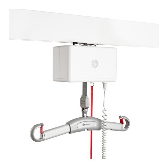
RiseAtlas450M,
with QuickTrolleySystem
SystemRoMedic
TM
RiseAtlas450M with QuickTrolleySystem has been developed, for use in combination with the appropriate lifting acces-
sories, for transferring patients conveniently between two locations. The ceiling lift unit is installed on the appropriate rail
system to cover lifting needs in the given situation. The rail system may consist of a straight rail, with or without curves,
or a traverse system. It is also possible to transfer patients between two rooms using RiseAtlas. The QuickTrolley func-
tion facilitates mounting and dismounting of the lift unit on the rail.
Handicare's SystemRoMedic product series includes a range of lifts, slings and other accessories. SystemRoMedic
adopts a holistic approach to patient transfers and is organized in four categories: transfer, positioning, support and
lifting.
Functional inspection
Visual inspection
Inspect lift functions regularly. Check to ensure that product is free from damage.
Before use:
Ensure that the product is correctly assembled.
Check rail end stops.
Check slingbar connection and safety latch function.
Check lifting movement.
Always read the manual
Always read the manuals for all assistive devices used during a transfer.
Keep the manual where it is accessible to users of the product.
The user/attendant shall be trained professional with thorough understanding of the equipment and lifting of disabled
persons.
Manual nr: 706-En Ver. 4 140820
Manual - English
50100057 (RiseAtlas450M)
50100051 (RiseAtlas450M, high humidity)
SWL:
RiseAtlas450: 205 kg/450 lbs
Advertisement
Table of Contents

Subscribe to Our Youtube Channel
Related Manuals for Handicare SystemRoMedic RiseAtlas450M QuickTrolleySystem


Summary of Contents for Handicare SystemRoMedic RiseAtlas450M QuickTrolleySystem
- Page 1 Handicare’s SystemRoMedic product series includes a range of lifts, slings and other accessories. SystemRoMedic adopts a holistic approach to patient transfers and is organized in four categories: transfer, positioning, support and lifting.
-
Page 2: Table Of Contents
Table of contents Installation ...................3-12 - Unpacking and check................- Transport and storage ............................... - Installing the lift unit - Charging the lift unit ................7-10 - Using QuickTrolleySystem ..............11 - Different rail systems ................12 - Final inspection ..................12 Using the product ..............13-18 - Important information ................13 - Before use ...................13... -
Page 3: Installation
NOTE! The lift unit and carriage must be installed and inspected by authorized personnel according to instructions issued by Handicare AB. Periodic inspection must be performed at least once yearly. Use only original spare parts. Service and maintenance must be performed according to instructions in the manual. - Page 4 The strap is cut with scissors and singed at the end as to prevent unravel. Handicare recommends a height of 180 cm/70 inches above the floor. Assembly of charger unit...
- Page 5 Assembly of the trolley Clearence hole for safety pin To be able to mount and dismount the lift unit from the rail with the QuickTrolleySystem, the saftey pin, marked red in fig 1, needs a clearence hole in the rail that enables the saftey pin to slide up and down. Mounting and dismounting the lift unit from the rail will only be possible at the position where the clearence hole has been made.
- Page 6 If the desired position for the lift unit is not parallell to the rail the quick trolley release bracket, marked red in fig 5, can be adjusted by 45-degree angle intervals. Open the cover by removing the two screws at the top. More detailed information can be find in the service manual for RiseAtlas450.
-
Page 7: Charging The Lift Unit
Charging the lift unit RiseAtlas can be used with three different charging systems: 1. Charger station for charging via hand control (Standard version for 50100057) 2. In-rail charging (Accessory for 50100057) 3. End-point charging (Standard version for 50100051, accessory for 50100057) RiseAtlas is charged with a charger unit that is connected to the charger cables via a DC outlet. - Page 8 Alteration of the charging method must be performed by authorized personnel according to instructions issued by Handicare AB. 1) Set the charging points for in-rail charging; the charger plate is not secured with the spring pins, see fig 1. To set the charging points for in-rail charging, remove the spring pins that hold the charger plate in place.
- Page 9 Alternative 3: End-point charging (Standard version for article number 50100051 and accessory for article number 50100057) If the end-point charging option is chosen, the lift unit must be fitted with a charger contact (70200062). The charger that is included with the lift unit is used. It is connected to the charger rails in the same way as the charger station, see section Charger station for charging via hand control.
- Page 10 Battery status, charger station The battery symbol lights green when battery capacity exceeds 50%. If the battery symbol blinks orange when the lift is started, the battery needs to be charged. If the battery symbol lights orange and a beep is heard when the lift is run up, the battery needs to be charged immediately.
-
Page 11: Using Quicktrolleysystem
Using QuickTrolleySystem Ensure that the emergency stop is activated and place the lift unit in the rail by inserting the QuickTrolley T-bracket into the trolley. Then rotate the lift unit 90 degrees to lock the QuickTrolleyReleaseBracket into the trolley, picture 1-4 below. Ensure that the lift unit slides in place and that it can be moved along the rail. -
Page 12: Different Rail Systems
Final inspection • The RiseAtlas lifting unit must be installed and first-time inspected by authorized personnel (inspector) in accordance with the installation instructions provided by Handicare AB. Periodic inspection of the equipment should be undertaken at least once a year. Original spare parts should be used and service/maintenance of the equipment should be in ac- cordance with the manual. -
Page 13: Using The Product
Using the product Important information • The user/attendant shall be trained professional with thorough understanding of the equipment and lifting of disabled persons. It is important that proper accessories and techniques are used by the user/attendant and it is also very important that a patient never is left unattended in a lifting situation. • Warranty does not apply if repairs or alterations are made to the lift by personnel who are not authorized. • RiseAtlas must not come in direct contact with water. • RiseAtlas must not be charged in a wet room (article no. 50100057). • To ensure optimal function, the lift must be inspected regularly. See section on Maintenance. -
Page 14: Safe Working Load
Safe working load SWL: Different products on the same lift system (lift unit, sling and other lifting accessories) may have different allowable safe working loads. The lowest allowable safe working load always determines the safe working load of the assembled system. -
Page 15: Hand Control
Hand control Connection of hand control to lift unit: The outlet for the hand control is under if the lift unit, fig 1. Press the plug in securely. Raising/lowering The buttons with the black arrows raise and lower the lift strap. Raising/lowering is interrupted as soon as pressure on the buttons is released, fig 2. -
Page 16: Information Panel
Preventative service/maintenance The symbol for service/maintenance lights up automatically when the lift unit has been used for 12 months. Contact an authorized Handicare service technician for maintenance and resetting. SystemRoMedic M A N U A L... -
Page 17: Emergency Stop
Always ensure that emergency lowering is done in an appropriate location. NOTE! Lowering is very slow. Re-setting manual emergency lowering/raising: Contact an authorized Handicare service technician. Do not use the lift unit. Allen key SystemRoMedic M A N U A L... -
Page 18: Trouble-Shooting
- that the directional indicators on the buttons, arrow up and arrow down, are correct. If unusual sounds are heard: - try to locate the source of the sound. Take the lift unit out of service and contact your Handicare dealer. Symbol indication: The symbol indicates that the lift unit must be inspected. -
Page 19: Accessories
Accessories SystemRoMedic Slings SystemRoMedic offers a wide variety of functional and comfortable high quality lifting slings adapted to meet the different requirements of all kinds of lifting situations and users. The lifting slings are available in four different materials and in sizes ranging from XXS to XXL. All models are safe and very easy to use. -
Page 20: Maintenance
30 % to 75%. The air pressure shall be between 700 and 1060hPa. Service agreements Handicare offers the possibility of service agreements for maintenance and regular testing of your lift. Contact your local Handicare representative. -
Page 21: Technical Information
Technical information Article no.: 50100057 Lift motor: 24VDC Lifting speed: 3,9 cm/s (5,0 cm/s), 1.5 inch/s (2.0 imch/s) with (without) load Charger IN: Mascot 2215 100-240VAC/ 50-60Hz Max 0,9A. Charger OUT: 41 VDC ±0,3 Max 0,9A Batteries: 24 VDC (20st 1,2VDC) 3,2 Ah. NIMH20XA3200 Motor cover: Flame-resistant ABS plastic Hand control:... -
Page 22: Technical Information
Technical information Article no.: 50100051 Lift motor: 24VDC 3,9 cm/s (5,0 cm/s), 1.5 inch/s (2.0 imch/s) with (without) load Lifting speed: Charger IN: Mascot 2215 100-240VAC/ 50-60Hz Max 0,9A. Charger OUT: 41 VDC ±0,3 Max 0,9A Batteries: 24 VDC (20st 1,2VDC) 3,2 Ah. NIMH20XA3200 Motor cover: Flame-resistant ABS plastic Hand control:... -
Page 23: Detailed Description
Detailed description Article no.: 50100057 1. Outlet for hand control 2. Hand control 3. Lift strap 4. Emergency stop and electrical emergency lowering 5. Manual emergency lowering/raising (inside cover) 6. Control panel A. Rail 6.4-16.0 cm/2,5-6,2 inch B. Lift unit overall height 16.0 cm/6,2 inch C. - Page 24 Contact your local distributor if you have any questions about the product and its use. See www.handicare.com for a complete list of distributors. Always make sure that you have the right version of the manual. The most recent editions of manuals are available for downloading from our website, www.handicare.com...
Need help?
Do you have a question about the SystemRoMedic RiseAtlas450M QuickTrolleySystem and is the answer not in the manual?
Questions and answers