Table of Contents
Advertisement
RiseAtlas450/RiseAtlas625
SystemRoMedic
TM
Valid from serial number:
515120001
515220001
515340001
515720001
515820001
515920001
516020001
RiseAtlas is a ceiling lift motor unit (stationary lift unit) that is intended to be used in combination with appropriate
accessories, such as rail systems and slings, to lift disabled people. RiseAtlas450 (205 kg) and RiseAtlas625 (285 kg) are
both available in two basic versions with different ways of travelling along the rail. The M-version is manually transferred
along the rail, while T-version has built-in transfer motor and thereby powered transfer in the rail.
This service manual is a technical document only to be used by trained and authorized service technicians.
The RiseAtlas lifting unit and the RiseAtlas Trolley must be installed and first-time inspected by authorized personnel,
inspector or service technician, in accordance with the installation instructions provided by Handicare AB. Periodic
inspection of the equipment should be done at least once a year. Original spare parts should be used and service/
maintenance of the equipment should be in accordance with manual.
Keep the service manual where it is accessible.
The service manual is a document to be used by technicians in combination with training.
RiseAtlas and accessories are made for indoor use and protection against water is IPX4.
It is strongly prohibited to change or modified the original RiseAtlas product unless stated in this manual.
Manual nr: 631 En Ver. 4 151124
Service manual - English
RiseAtlas art. no.
50100051
50100052
50100053
50100057
50100058
50100059
50100060
SWL
RiseAtlas450: 205 kg/450 lbs
RiseAtlas625: 285 kg/625 lbs
Advertisement
Table of Contents

Related Manuals for Handicare SystemRoMedic RiseAtlas450


Summary of Contents for Handicare SystemRoMedic RiseAtlas450
- Page 1 The RiseAtlas lifting unit and the RiseAtlas Trolley must be installed and first-time inspected by authorized personnel, inspector or service technician, in accordance with the installation instructions provided by Handicare AB. Periodic inspection of the equipment should be done at least once a year. Original spare parts should be used and service/ maintenance of the equipment should be in accordance with manual.
-
Page 3: Table Of Contents
Table of Contents 1. Use of RiseAtlas by user/attendant 1.1 Basic description 1.2 Basic product safety 1.3 Before use 1.4 Trouble-shooting 1.5 Emergency situation 1.6 Others 2. Installation, assembly, inspection, service and maintenance of RiseAtlas by technicians 2.1 Basic product safety 2.2 Installation or assembly 2.3 Inspection 2.4 Service and maintenance... -
Page 4: Use Of Riseatlas By User/Attendant
Using of RiseAtlas must be done by trained professionals with thorough understanding of the equipment and lifting techniques of disabled people. Training is done by Handicare (or Handicare distributor) and user/attendant shall always read the manuals for all assistive devices before lifting /transfer. -
Page 5: Before Use
1.3 Before use The user/attendant shall perform following inspections before use. • Inspect the lift for signs of wear and damage. • Check battery charge level. • Check that correct accessories are used and correct attachment has been made. • Ensure that lifting environment is safe. -
Page 6: Installation, Assembly, Inspection, Service And Maintenance Of Riseatlas By Technicians
Installation, assembly, inspection, service and maintenance of RiseAtlas must be done by authorized personnel in accordance with instructions provided by Handicare AB. An authorized person (service technician, inspector etc.) shall be trained by Handicare (or Handicare distributor) and shall be well acquainted with the design, use and care of the lift. -
Page 7: Warranty
Every action taken on the equipment shall be noted in the logbook and logbook shall be kept, together with manual, readily accessible close to equipment. Estimated life length for equipment is at least 10 years. 2.5 Warranty Warranty for Handicare equipment does not include wear and tear parts. Equipment shall be serviced and maintenance according to manual. SystemRoMedic... -
Page 8: Access Inside Riseatlas
3. Access inside RiseAtlas Only authorized technicians shall open the covers of RiseAtlas in order to get access inside RiseAtlas. The two covers of RiseAtlas are opened by removing two screws at the top by hand and pull the covers gently apart. Closing the cover, Close the two covers carefully and ensure that cables and wirings are not squeezed by covers. -
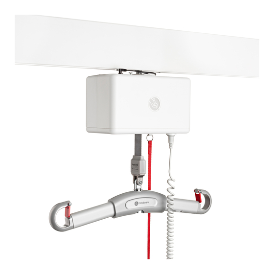
Page 9: Main Parts Of Riseatlas
4. Main parts RiseAtlas In order to get access to the main parts, please see chapter 3. The main parts of RiseAtlas are: 1. Hand control The RiseAtlas is turned Off/On with the hand control and also the lift movement Up/Down is controlled by hand control. Please see chapter 9.1 Test and/or replace hand control. - Page 10 h. Hand control input plug, The hand control connects to the hand control input plug and it is a integrated part of bottom plate. Please see chapter 9.4 for replacement. i. Emergency stop, The emergency stop device shuts off power between battery and PCB when activated. It also functions as an electrical emergency lowering when pulled out.
- Page 11 SystemRoMedic S E R V I C E M A N U A L...
- Page 12 SystemRoMedic S E R V I C E M A N U A L...
- Page 13 5. Advanced trouble-shooting RiseAtlas Only authorized technicians shall perform this operation on RiseAtlas and thorough understanding of the product is a must. Access inside RiseAtlas is described in chapter 3 and necessary tools are described in chapter 7. It is understood that ordinary Trouble-shooting, please see chapter 1.4, has been performed before the Advanced trouble-shooting starts.
-
Page 14: Resetting The Service Indicator
D. Check limit switches for functionality by using a finger and voltmeter. - The micro switch up is normally open (no signal) and when activated, by hook or tilted band, it should give a signal (closing) and stop winding movement. o Bad switch should be changed. -
Page 15: Tool List
7. Tool list RiseAtlas These are the recommended tools to RiseAtlas in order to perform basic service: Torx key no.: 6 and 10 Allen key size no.: 2, 2.5 and 5. Pliers. Circlip pliers. Phillips Screwdrivers, small. Flat-bladed Screwdriver, small. Voltmeter. -
Page 16: Spare Part List
1 set 2 x casing top half RiseAtlas (not for 2 x knurled screw high DIN464 50100051) M3x8 81000003 2 x label Handicare round 81000009 Wheels 1 pair 2 x circlip 10mm 2 x trolley wheel 2 x key 81000032... - Page 17 Spare parts no. Article Unit Components 81000017 Bottom plate incl. 1 pce 1 x diagnostic display display 6 x Screw 2,9x9,5 fz 4 x threaded insert 1 x emergency light 1 x interface plate 2 x battery casing 4 x screw M3x6 fzb 1 x control jack RiseAtlas 1 x night light cable RiseAtlas 1 x diagnostic cable RiseAtlas...
-
Page 18: Changing Spare Parts Riseatlas
9. Changing spare parts RiseAtlas 9.1 Test and/or replace hand control, spare part no: 81000004 or 81000005 The test and/or replacement of hand control can be performed without opening the RiseAtlas cover. Unplug the hand control from the lift unit by pulling and wiggling the connection plug by hand. - Check that the entire hand control cable is free from damage and that connection grommets are intact. - Page 19 After removing the RiseAtlas cover, check the following; - All cables and connectors are correctly attached. o If loose connector is found, attach correctly and reassemble the RiseAtlas covers. - Disconnect the wiring of the battery and disassemble the batteries from the plastic brackets, see picture. o Measure cross the black and red wire on the battery side, should be 24 –...
- Page 20 9.3 Replace circuit board, spare part no: 81000002 or 81000033 The circuit board, spare part no: 81000002, 81000033 is used for the RiseAtlas. The board Flex-CTH_V2-05a is delivered with the available off hardware and program. Can only be used with right thermo cable. 9.3.1 Replace circuit board for RiseAtlas, The spare part circuit board, 81000002 or 81000033 (depending on model), is the latest version provided and this...
- Page 21 Change of circuit board RiseAtlas, The picture shows an example of RiseAtlas circuit board RiseAtlas450MQ (manual motor). Important is to disconnect and connect all wirings properly – use marking if necessary. After removing the RiseAtlas cover, please check and perform the following operations: •...
- Page 22 • Attach the new PCB-card, spare part no: 81000002, by; Use the existing plastic clips and ensure correct connection. Attach wiring according to disassembly. Ensure correct DIP-switch configuration. • Attach the battery and make a functional check before closing the cover of lift unit. If everything is OK and functional –...
- Page 23 9.4 Replace bottom plate incl. display, RiseAtlas. Spare part no: 81000017 In order to replace bottom plate there is a need to open the RiseAtlas cover, see chapter 3 Access inside RiseAtlas. Handling of electronics shall be performed with caution and the use of ESD protection. The bottom plate incl.
- Page 24 9.5 Strap change RiseAtlas. Spare part no: 81000003 Remove covers (see chapter 3) Remove h-adapter Extract strap with hand controll or emergency lowering Deactivate micro switch in order to extract all strap until opening in shaft is revealed Remove batteries and main board (see chapter 9.2, 9.3) Remove emergency lowering strap Remove interface plate Unscrew all four screws (pilar!)
- Page 25 Remove battery holder on side with big gear Remove micro switches that regulate the strap length Remove the bottom plate from the chassis, do not contaminate the strap with grease Remove the strap guide Use caution while removing the guide, the four springs can easily fall off Remove the strap from the shaft by taking out the safety pin and pulling...
- Page 26 Mount the h-adapter, do not forget the safety pin Make a verification inspection (see chapter 11) A functional, safety and load test, according to 2.3.2, 2.3.3 and 2.3.4, shall be performed of RiseAtlas to ensure proper function and notes of change should be presented in the lift logbook. The old parts can be recycled at the nearest recycling station.
- Page 27 10. Component list - RiseAtlas 50100057 SystemRoMedic S E R V I C E M A N U A L...
- Page 28 RiseAtlas 50100051 SystemRoMedic S E R V I C E M A N U A L...
- Page 29 RiseAtlas 50100058, 50100061 SystemRoMedic S E R V I C E M A N U A L...
- Page 30 RiseAtlas 50100059 SystemRoMedic S E R V I C E M A N U A L...
-
Page 31: Inspection Riseatlas
11. Inspection RiseAtlas Inspection of shall be performed by authorized personnel and inspections are to be made at the following scenarios. • First-time inspection – inspection to be performed when first-time installation or first-time assembly has been made to equipment. Inspection includes all categories below. •... - Page 32 Safety testing of RiseAtlas, Emergency stop device. Emergency lowering, mechanical and electrical. Check all connection points, both H-adapter and sling bar safety latches. Load and speed testing of RiseAtlas (performance), Every first-time and periodic inspection shall include a working load test (safe working load) of one (1) lifting cycle with the maximum load.
-
Page 33: Inspection Check List Riseatlas
Mechanical and electrical. Connection points In accordance with ISO 10535:2006 Annex A-Periodic inspection Date of inspection: Test-loaded with: Sign installer: Sign Customer: © Handicare AB • www.handicare.com SystemRoMedic S E R V I C E M A N U A L... - Page 34 +50 °C -10 °C 700 hPa Service agreements Handicare offers service agreements for maintenance and regular testing of your lift unit. Contact your local Handicare representative. Serial number SystemRoMedic S E R V I C E M A N U A L...
-
Page 35: Technical Information
Technical Information Article no.: 50100058, 50100060 Lift motor 24 V DC Lifting speed 3,9 cm/s (5,0 cm/s), 1.5 inch/s (2.0 imch/s) with (without) load Charger IN Mascot 2215 100-240 V AC/ 50-60 Hz Max 0,9 A. Charger OUT 41 V DC ± 0,3 Max 0,9 A Batteries 24 VDC (20st 1,2VDC) 3,2 Ah. - Page 36 Article no.: 50100058, 50100060 Lift motor 24 V DC Lifting speed 3,9 cm/s (5,0 cm/s), 1.5 inch/s (2.0 imch/s) with (without) load Charger IN Mascot 2215 100-240 V AC/ 50-60 Hz Max 0,9 A. Charger OUT 41 V DC ± 0,3 Max 0,9 A Batteries 24 VDC (20st 1,2VDC) 3,2 Ah.
- Page 37 Article no.: 50100057 Lift motor 24 V DC Lifting speed 3,9 cm/s (5,0 cm/s), 1.5 inch/s (2.0 imch/s) with (without) load Charger IN Mascot 2215 100-240 V AC/ 50-60 Hz Max 0,9 A. Charger OUT 41 V DC ± 0,3 Max 0,9 A Batteries 24 VDC (20st 1,2VDC) 3,2 Ah.
- Page 38 Article no.: 50100051 Lift motor 24 V DC Lifting speed 3,9 cm/s (5,0 cm/s), 1.5 inch/s (2.0 imch/s) with (without) load Charger IN Mascot 2215 100-240 V AC/ 50-60 Hz Max 0,9 A. Charger OUT 41 V DC ± 0,3 Max 0,9 A Batteries 24 VDC (20st 1,2VDC) 3,2 Ah.
- Page 39 Article no.: 50100059 Lift motor 24 V DC Lifting speed 3,9 cm/s (5,0 cm/s), 1.5 inch/s (2.0 imch/s) with (without) load Charger IN Mascot 2215 100-240 V AC/ 50-60 Hz Max 0,9 A. Charger OUT 41 V DC ± 0,3 Max 0,9 A Batteries 24 VDC (20st 1,2VDC) 3,2 Ah.
-
Page 40: Detailed Description
Detailed description Article no.: 50100058, 50100060 1. Outlet for hand control 2. Hand control 3. Lift strap 4. Emergency stop and electrical emergency lowering 5. Manual emergency lowering/raising 6. Control panel A. Rail 64-160 mm B. Lift unit overall height 160 mm C. - Page 41 Article no.: 50100057 1. Outlet for hand control 2. Hand control 3. Lift strap 4. Emergency stop and electrical emergency lowering 5. Manual emergency lowering/raising 6. Control panel A. Rail 64-160 mm B. Lift unit overall height 160 mm C. Installation height 230 mm Installation height on SlingBar M, 327 mm Article no.: 50100051 1.
-
Page 42: Control Panel
Article no.: 50100059 1. Outlet for hand control 2. Hand control 3. Lift strap 4. Emergency stop and electrical emergency lowering 5. Manual emergency lowering/raising 6. Control panel A. Rail 64-160 mm B. Lift unit overall height 200 mm C. Installation height 270 mm Installation height on SlingBar M, 367 mm NAME DATE... - Page 43 14. Logbook RiseAtlas • RiseAtlas450 QuickTrolley, High humidity 50100051 • RiseAtlas450T SmartPark 50100052 • RiseAtlas625T SmartPark 50100053 • RiseAtlas450M QuickTrolley 50100057 • RiseAtlas450T 50100058 • RiseAtlas625T QuickTrolley 50100059 • RiseAtlas625T 50100060 Start by filling in the Installation Certificate Over head Systens as soon as the equipment is installed. It is important that the installer/service technician signs the document.
- Page 44 SystemRoMedic S E R V I C E M A N U A L...
- Page 45 Logbook: Observation (by the user or technician): ……………………………………………………………..Corrective action (service or maintenance): ……………………………………………………………… Inspection: □ First-time Inspection □ Periodic Inspection □ Verification Inspection Date:......Custom.no: ..... Order.no: ..... Equip.no: ..... Lift has been approved (Yes/No) Remarks: Performed by:..........Sign customer:............Logbook: Observation (by the user or technician): ……………………………………………………………..
- Page 46 Logbook: Observation (by the user or technician): ……………………………………………………………..Corrective action (service or maintenance): ……………………………………………………………… Inspection: □ First-time Inspection □ Periodic Inspection □ Verification Inspection Date:......Custom.no: ..... Order.no: ..... Equip.no: ..... Lift has been approved (Yes/No) Remarks: Performed by:..........Sign customer:............Logbook: Observation (by the user or technician): ……………………………………………………………..
- Page 47 SystemRoMedic S E R V I C E M A N U A L...
- Page 48 Please contact your local Handicare and SystemRoMedic™ representative. A complete list of all our partners with their contact details can be found on our website; www.handicare.com. Handicare offers solutions and support to increase the independence of disabled or elderly people as well as to improve the convenience of those who are caring for them.
Need help?
Do you have a question about the SystemRoMedic RiseAtlas450 and is the answer not in the manual?
Questions and answers