Moxa Technologies ioThinx 4530 Series Hardware User Manual
Hide thumbs
Also See for ioThinx 4530 Series:
- Hardware user manual (22 pages) ,
- User manual (20 pages) ,
- Quick installation manual (12 pages)
Table of Contents
Advertisement
Quick Links
Download this manual
See also:
User Manual
Advertisement
Table of Contents

Related Manuals for Moxa Technologies ioThinx 4530 Series


Summary of Contents for Moxa Technologies ioThinx 4530 Series
- Page 1 4530 Series Hardware User’s Manual Version 1.0, March 2019 www.moxa.com/product © 2019 Moxa Inc. All rights reserved.
- Page 2 4530 Series Hardware User’s Manual The software described in this manual is furnished under a license agreement and may be used only in accordance with the terms of that agreement. Copyright Notice © 2019 Moxa Inc. All rights reserved.
- Page 3 Safety Symbols DANGER Indicates a high-risk, imminently hazardous situation which, if not avoided, will result in death or serious injury. WARNING Indicates a moderate risk, which, if not avoided can cause a potentially hazardous situation. CAUTION Indicates a low-risk, potentially hazardous situation which, if not avoided, may result in minor or moderate injury.
-
Page 4: Table Of Contents
Table of Contents Preface .............................. 1-1 Revision History ..........................1-2 Relevant Models ..........................1-2 Package Contents ..........................1-2 Usage Scenarios ..........................1-2 Hardware and Software Requirements ....................1-3 Safety Precautions ..........................1-3 Additional Resources ........................... 1-4 Product Overview ..........................2-1 Specifications ............................. -
Page 5: Preface
Preface In this chapter, we explain the scope of and how to use this document. The following topics are covered in this chapter: Revision History Relevant Models Package Contents Usage Scenarios Hardware and Software Requirements ... -
Page 6: Revision History
For better control precision, the Moxa Industrial Linux operating system gives the ioThinx 4530 Series the capability to handle computations and control actions at the same time. In addition, the ioThinx 4530 Series helps manage data privacy, and supports both hardware privacy features, such as TPM (Trusted Platform Module, which is optional), and software privacy features, such as secure boot, to help users implement cybersecurity protections. -
Page 7: Hardware And Software Requirements
4530 Series Hardware Manual Preface Hardware and Software Requirements You will need the following hardware and software to use the ioThinx 4530 Series. • A power source that provides 12 to 48 VDC, and power wires • A PC running Linux OS (we recommend Debian 9, Kernel 4.4) and an Ethernet cable •... -
Page 8: Additional Resources
4530 Series Hardware Manual Preface WARNING Check the voltage or current of the sensors or loads. Make sure the voltage and/or current indicated on the sensors or loads corresponds to the specifications of your 45M module before you connect the device. -
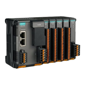
Page 9: Product Overview
Product Overview In this chapter, we give an overview of each ioThinx 4530 Series product. The following topics are covered in this chapter: Technical Data Common Specifications Appearance Front View Physical Dimensions LED Indicators... -
Page 10: Specifications
4530 Series Hardware Manual Product Overview Specifications NOTE The latest specifications for Moxa’s products can be found at https://www.moxa.com. Appearance Front View Physical Dimensions... -
Page 11: Led Indicators
4530 Series Hardware Manual Product Overview LED Indicators Label Usage Color Action System Power Green On: Power on Off: Power off Field Power Green On: Power on Off: Power off System (kernel) 1 Green/Red Green: System ready Green (blinking): System is booting up... -
Page 12: Hardware Installation
Hardware Installation In this chapter, we describe how to install ioThinx 4530 Series products. The following topics are covered in this chapter: Wiring System and Field Power System Power Field Power Wiring Ethernet Ports Wiring Serial Port(s) ... -
Page 13: Wiring System And Field Power
4530 Series Hardware Manual Hardware Installation Wiring System and Field Power Wire range: 12 to 26 AWG (Ferrule diameter: 2.0 to 0.4 mm) Wire strip length: 10 mm Unit: mm (in.) CAUTION Be sure to note the maximum possible current for each power wire and common wire. Observe all electrical codes dictating the maximum current allowable for each wire size. -
Page 14: Field Power
4530 Series Hardware Manual Hardware Installation The total system current is 1.594 A, which is greater than 1 A. Therefore, an additional 45MR-7210 is needed. NOTE Install the 45MR-7210 to the left hand side of the module where the power consumption would be exceeded. -
Page 15: Wiring Serial Port(S)
4530 Series Hardware Manual Hardware Installation Wiring Serial Port(s) Wire range: 16 to 28 AWG (Ferrule diameter: 1.2 to 0.3 mm) Wire strip length: 9.0 mm Unit: mm (in.) RS-232 RS-422 RS-485 (P1/P2) TXD+ DATA1+ TXD- DATA1- RXD+ DATA2+... - Page 16 4530 Series Hardware Manual Hardware Installation Step 1: Open the card cover Console port for the ioThinx Series Step 2: Attach the 4-pin serial console cable to the console port. The following diagram shows the 4-pin serial connector and pin connections.
- Page 17 4530 Series Hardware Manual Hardware Installation 4. Click Profile Open. 5. Specify which COM port is connecting to the Moxa controller, and then use the following configuration settings: 115200, 8, none, 1.
- Page 18 4530 Series Hardware Manual Hardware Installation 6. Click on the Terminal tab and configure the Terminal Type to VT100. Click OK to proceed. 7. The serial console will be displayed on the terminal screen.
-
Page 19: Grounding The Unit
4530 Series Hardware Manual Hardware Installation Grounding the Unit This device has two ground pins. One pin is for system power and the other pin is for field power. Connecting the System Power Ground The system power ground connector is at the back of the unit. Once the device has been installed on a DIN rail, the system power ground connector will connect to the DIN rail. -
Page 20: Mounting The Unit
4530 Series Hardware Manual Hardware Installation CAUTION Be sure to note the maximum possible current for each power wire and common wire. Observe all electrical codes dictating the maximum current allowable for each wire size. If currents exceed the maximum rating, the wires will overheat, which could cause serious damage to your equipment. -
Page 21: Removing The Unit From A Din Rail
4530 Series Hardware Manual Hardware Installation INFORMATION When the I/O module is inserted into the correct position, the connection between the internal bus and the previous module is established. Removing the Unit from a DIN Rail Take the following steps to remove the unit from a DIN rail. -
Page 22: Installing Covers On The Device And The Right-Most I/O Module
4530 Series Hardware Manual Hardware Installation Installing Covers on the Device and the Right-Most I/O Module Insert the covers on the left side of the device and on the right side of the I/O module that is installed furthest to the right. Make sure the covers cover the internal bus of the module. -
Page 23: Horizontal Installation
4530 Series Hardware Manual Hardware Installation Horizontal Installation Before installing the device, ensure there is enough space around the device so that it can dissipate heat. In order to ensure the device works properly, we suggest reserving the space shown in the figure below.
Need help?
Do you have a question about the ioThinx 4530 Series and is the answer not in the manual?
Questions and answers