
Related Manuals for Moxa Technologies ioPAC 8500 series


Summary of Contents for Moxa Technologies ioPAC 8500 series
- Page 1 ioPAC 8500 Hardware User’s Manual Edition 3.0, September 2017 www.moxa.com/product © 2017 Moxa Inc. All rights reserved.
- Page 2 ioPAC 8500 Hardware User’s Manual The software described in this manual is furnished under a license agreement and may be used only in accordance with the terms of that agreement. Copyright Notice © 2017 Moxa Inc. All rights reserved. Trademarks The MOXA logo is a registered trademark of Moxa Inc.
-
Page 3: Table Of Contents
Table of Contents Introduction ............................1-1 Overview ............................1-2 Package Checklist ..........................1-2 Appearance and Dimensions ........................ 1-3 Appearance ..........................1-3 Dimensions (unit: mm(inch)) ......................1-4 Hardware Block Diagrams ........................1-5 ioPAC 8500 CPU Board Block Diagram .................... 1-5 Product Hardware Specifications ......................1-5 Product Selection Guide ....................... -
Page 4: Introduction
Introduction The following topics are covered in this chapter: Overview Package Checklist Appearance and Dimensions Appearance Dimensions (unit: mm(inch)) Hardware Block Diagrams ioPAC 8500 CPU Board Block Diagram Product Hardware Specifications Product Selection Guide ... -
Page 5: Overview
ESD protection, a -40 to 75°C operating temperature range, anti-vibration, hot-swappability of modules, two 10/100 Mbps Ethernet ports with two MACs (Port Trunking ready), and two 3-in-1 serial ports. With Moxa’s Active OPC Server and DA-Center, the ioPAC 8500 series provides a comprehensive solution for data acquisition and control applications in harsh environment. -
Page 6: Appearance And Dimensions
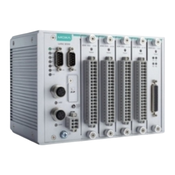
ioPAC 8500 Hardware Introduction Appearance and Dimensions Appearance ioPAC 8500 Modular Head The following figures depict ioPAC 8500 modular heads. There are two types of modular heads, both have dual Ethernet ports but one is RJ45 and the other is M12. -
Page 7: Dimensions (Unit: Mm(Inch))
ioPAC 8500 Hardware Introduction Dimensions (unit: mm(inch)) ioPAC 8500-2 ioPAC 8500-5 ioPAC 8500-9... -
Page 8: Hardware Block Diagrams
ioPAC 8500 Hardware Introduction Hardware Block Diagrams ioPAC 8500 CPU Board Block Diagram Product Hardware Specifications Product Selection Guide Model Name Description ioPAC 8500-2-RJ45-C-T 2 slots, RJ45, C/C++ ioPAC 8500-5-RJ45-C-T 5 slots, RJ45, C/C++ ioPAC 8500-9-RJ45-C-T 9 slots, RJ45, C/C++ ioPAC 8500-2-M12-C-T 2 slots, M12, C/C++ ioPAC 8500-5-M12-C-T... -
Page 9: Specifications
ioPAC 8500 Hardware Introduction Specifications Computer Main CPU: ARM9 based CPU, 32-bit/192 MHz I/O CPU: ARM Cortex M4 based CPU, 32-bit/80MHz OS: Linux Clock: Real-time clock with battery backup Memory: • SDRAM: 64 MB • Flash: 32 MB • SRAM: 256 KB (battery backup lasts for 1 week) •... - Page 10 ioPAC 8500 Hardware Introduction Mounting: DIN rail mounting (standard), wall mounting (optional) Connector: Spring-type terminal block Environmental Limits Operating Temperature: -40 to 75°C (-40 to 176°F) Storage Temperature: -40 to 85°C (-40 to 185°F) Ambient Relative Humidity: 5 to 95% (non-condensing) Shock: IEC 60068-2-27 Vibration: IEC 60068-2-6 Altitude: Up to 2000 m...
-
Page 11: Installation
Installation This chapter includes instructions on how to install the ioPAC 8500. The following topics are covered in this chapter: Basic Installation DIN Rail Installation Procedure Wall-Mounting Kit Installation Procedure Module Installation Procedure (Power-Off) Module Installation Procedure (Power-On) ... -
Page 12: Basic Installation
ioPAC 8500 Hardware Installation Basic Installation DIN Rail Installation Procedure Installing the ioPAC 8500 on a DIN Rail The DIN rail attachment plate should already be fixed to the back panel of the ioPAC 8500 when you take it out of the box. -
Page 13: Wall-Mounting Kit Installation Procedure
ioPAC 8500 Hardware Installation Wall-Mounting Kit Installation Procedure If required for your application, the wall-mounting kit can be purchased separately as an optional accessory. STEP 1: Use screws to attach the wall-mounting kit to the back of the ioPAC 8500, as shown below: STEP 2: Use screws to fix the wall-mounting kit to a wall. -
Page 14: Module Installation Procedure (Power-Off)
ioPAC 8500 Hardware Installation Module Installation Procedure (Power-Off) Moxa’s ioPAC 8500 controllers come with 2, 5, or 9 slots for 85M-series modules. Use the following procedure to install modules when your system is powered off. Step1: Install the module into the ioPAC 8500 system. The module’s PCB should align with the edge of the frame. -
Page 15: Installing A Microsd Card
ioPAC 8500 Hardware Installation ATTENTION This product is intended to be supplied by a Listed Power Unit with output marked “LPS” and rated for 9-48 VDC (minimum requirements). For railway rolling stock applications, these devices must be supplied by a galvanic isolated power supply with design based on the EN 50155 standard. -
Page 16: Iopac 8500 Led Indicators
ioPAC 8500 Hardware Installation ioPAC 8500 LED Indicators There are 9 LEDs on the ioPAC controller. ioPAC 8500 C/C++ Version ioPAC 8500 C/C++ Version... -
Page 17: System Leds
ioPAC 8500 Hardware Installation Category Label Usage On: Power On System Power Off: Power Off System (Kernel) Green: System Ready Blinking Green: System is booting up Ready Red: System error, firmware upgrade, or reset procedure underway System Blinking Red: Factory reset triggered Expansion Green: Expansion configuration OK Red: Expansion configuration failed... -
Page 18: Iec-61131-3 Compliant Leds: R/S And Err
ioPAC 8500 Hardware Installation IEC-61131-3 Compliant LEDs: R/S and ERR The ioPAC controller supports IEC-61131-3-compliant Run/Stop and Error (ERR) LEDs for ISaGRAF-specific notifications. These LEDs are not user configurable. Communication LEDs P1 and P2 The ioPAC controller comes with two serial connections. P1 and P2 represent the status of each serial connection. -
Page 19: Toggle Switch: Factory Reset Process
ioPAC 8500 Hardware Installation Toggle Switch: Factory Reset Process Use the following procedure to reset the ioPAC to the factory defaults. Note that when you reset the ioPAC, all of your tag definitions, software programs, and files will be deleted, and the service and runtime engine will be restarted. - Page 20 ioPAC 8500 Hardware Installation RJ45 Ethernet Connector The ideal maximum cable length of a 10/100BaseT connection is 100 m (350 feet), but the actual limit could be longer or shorter depending on the amount of electrical noise in the environment. To minimize the amount of noise, Ethernet cables should not run parallel to power cables or other types of cables that generate electrical noise.
- Page 21 ioPAC 8500 Hardware Installation M12 (4-pin, M) to M12 (4-pin, M) Cross-Over Cable Wiring M12 (4-pin, M) to M12 (4-pin, M) Straight-Through Cable Wiring M12 (4-pin, M) to RJ45 (8-pin) Cross-Over Cable Wiring M12 (4-pin, M) to RJ45 (8-pin) Straight-Through Cable Wiring ATTENTION Configuring the two LAN ports on the same ioPAC RTU controller to the same network domain (e.g., 192.168.1.1 and 192.168.1.2) is not recommended.
-
Page 22: Serial Connectivity
ioPAC 8500 Hardware Installation Port Trunking The ioPAC 8500 RTU controller has a Port Trunking function (active backup mode) that can convert two LAN-port IP addresses into one virtual IP address for easy SCADA integration and Ethernet redundancy. In the following diagram, both LAN ports on each ioPAC RTU controller are connected to a managed switch on an Ethernet network running SCADA software. -
Page 23: Serial Console (Debug Port)
ioPAC 8500 Hardware Installation Serial Console (Debug Port) The serial console gives users a convenient way of connecting to the RTU controllers. This method is particularly useful when using the computer for the first time. The serial console is also effective for connecting the Moxa RTU controllers when you do not know target network settings and IP addresses. - Page 24 ioPAC 8500 Hardware Installation 5. Specify which COM port is connecting to the Moxa RTU, and use the following configuration settings: 115200, 8, none, 1. 6. Click on the Terminal tab and configure the Terminal Type to VT100. Click OK to proceed. 7.
-
Page 25: Battery
ioPAC 8500 Hardware Installation Battery The ioPAC RTU controller is equipped with one built-in, rechargeable VL2020 3V battery for the SRAM and one BR2032 3V non-rechargeable battery for the Real Time Clock (RTC). • Rechargeable battery (VL2020) for SRAM Sustains at least 1 week without power supply ... -
Page 26: The Rtuxpress Utility
The RTUxpress Utility In this chapter, we introduce Moxa’s RTUxpress Utility. The ioPAC Series can be managed and configured over an Ethernet using RTUxpress, which provides easy access to all status information and ready-to-run service settings. The following topics are covered in this chapter: ... -
Page 27: Rtuxpress Introduction
ioPAC 8500 Hardware The RTUxpress Utility RTUxpress Introduction Moxa RTUxpress is a user-friendly and intuitive offline configuration tool for configuring Moxa’s ioPAC Programmable Controllers. RTUxpress is provided free of charge, and can be upgraded for free when future upgrades become available. RTUxpress has a user-friendly interface for device setup, tag management, and service configuration. -
Page 28: Quick Start
ioPAC 8500 Hardware The RTUxpress Utility Quick Start When you start RTUxpress, click on New Project, Open Project, or Help, located at the bottom of RTU Quick Start window. If do not want the Quick Start window to appear the next time you log in, select the Do not show this Quick Start again checkbox before proceeding. - Page 29 ioPAC 8500 Hardware The RTUxpress Utility The New CPU and Power Modules dialog allows you to specify the characteristics of the backplane module you are using. • Select the number of slots from the No. of Slots dropdown box. Three models are supported: 5 slots, 9 slots, 12 slots. •...
- Page 30 ioPAC 8500 Hardware The RTUxpress Utility Help Click the Help button to open the RTUxpress help utility, and then select a help topic from the left menu. Exit Click the Exit icon to close the RTUxpress utility.
-
Page 31: User Interface
ioPAC 8500 Hardware The RTUxpress Utility User Interface The RTUxpress interface is divided into six main areas: • Menu bar • Tool bar • Device configuration options • Service configuration options • Settings panel • Log message panel Menu Bar Tool Bar Settings Page Device and Service... - Page 32 ioPAC 8500 Hardware The RTUxpress Utility Menu Bar File: The following options are available under the File menu item: • New Project: Create a new RTUxpress project • Open Project: Open an existing RTUxpress project • Save Project: Save the RTUxpress project that is currently opened •...
- Page 33 ioPAC 8500 Hardware The RTUxpress Utility • Change CPU/Power Module: Change the CPU, Power, backplane settings for the RTUxpress project • Device Information: Get the device information for a particular device NOTE A username and password are required to retrieve device information. the default Username/Password is moxa/moxa for the ioPAC 8600-CPU30 series and root/root for other ioPAC series products.
- Page 34 ioPAC 8500 Hardware The RTUxpress Utility • Time Sync: Synchronize the device time with the PC’s time, or set the time manually • Modify Password: Modify the administrator password...
- Page 35 ioPAC 8500 Hardware The RTUxpress Utility • Reboot Device: Reboot the ioPAC Programmable Controller 3-10...
- Page 36 ioPAC 8500 Hardware The RTUxpress Utility • Firmware Update: Upgrade the ioPAC Programmable Controller’s firmware • Factory Reset: Reset all settings and configurations to default settings IEC 61131-3 Setting: a. Resource information: Indicates how many resources are supported by the ioPAC and whether or not the resources are running.
- Page 37 ioPAC 8500 Hardware The RTUxpress Utility • Online System Log: Users can change the system log settings online. NOTE Enabling the log will affect device performance. However, we recommend enabling it so that runtime details will be logged when the ioPAC experiences unexpected errors. •...
- Page 38 ioPAC 8500 Hardware The RTUxpress Utility Step 2: When the Log in window appears, enter the user name and password to log in. RTUxpress will open PuTTY to establish an SSH connection between the ioPAC and the PC. Step 3: When a connection has been established, the slot and API information will be displayed in the PuTTY window.
- Page 39 ioPAC 8500 Hardware The RTUxpress Utility Options: • Preferences: Allows you to configure the preferences shown below • Network Interface: Allows you to select the network interface Help: View Help: Opens the RTUxpress.chm help utility • Moxa ioPAC ISaGRAF Reference Manuals: Opens the Moxa_ioPAC_ISaGRAF.chm utility •...
- Page 40 ioPAC 8500 Hardware The RTUxpress Utility Tool Bar New Project: Create a new RTUxpress project Open Project: Open an existing RTUxpress project Save Project: Save a currently opened RTUxpress project Add Module: Add an ioPAC I/O module Delete Module: Delete an ioPAC I/O module Device Information: Get device information Time Sync: Device time synchronization Export Configuration to ioPAC: Export a configuration file to the ioPAC Programmable controller...
-
Page 41: Device And Service Configuration
ioPAC 8500 Hardware The RTUxpress Utility Device and Service Configuration Device Configuration is to configure ioPAC Programmable Controller settings and resources. You can configure the LAN, IO, an serial settings in the device’s configuration section. Since the product has a modular design, a module’s function settings will appear once the module has been added to the device. -
Page 42: Module Hardware Introduction
85M Module Hardware Introduction In this chapter, we provide the 85M modules’ specifications. The following topics are covered in this chapter: 85M Module Descriptions Common Specifications Module Specifications 85M-1602-T: 16 DIs, sink/source, 24 VDC, dry contact ... -
Page 43: Module Descriptions
ioPAC 8500 Hardware 85M Module Hardware Introduction 85M Module Descriptions The ioPAC 8500 controllers support the following modules. Model Name Description 85M-1602-T 16 DI, Sink/Source 85M-2600-T 16 DO, Sink 85M-3800-T 8 AI, 4-20 mA 85M-3810-T 8 AI, 0-10 V 85M-3801-T 8 AI 40 KHz, 4-20 mA 85M-3811-T 8 AI 40 KHz, 0-10 V... -
Page 44: Module Specifications
ioPAC 8500 Hardware 85M Module Hardware Introduction Module Specifications 85M-1602-T: 16 DIs, sink/source, 24 VDC, dry contact The 85M-1602-T modules is a 16-channel, sink/source, or dry contact type digital input module that support wide temperature and high isolation protection. Block Diagram Specifications The following are the 85M-1602-T module’s product specifications. - Page 45 ioPAC 8500 Hardware 85M Module Hardware Introduction Counter Frequency: 5 kHz Digital Filtering Time Interval: Software selectable (by 0.1 ms) Physical Characteristics Wiring: I/O cable, max. 16 AWG Connector: Spring type terminal block Environmental Limits Operating Temperature: -40 to 75°C (-40 to 176°F) Power Requirements Input Current: 363.6 mA @ 3.3 VDC MTBF...
- Page 46 ioPAC 8500 Hardware 85M Module Hardware Introduction Wiring Guide The following wiring guide is for the 85M-1602-T module. Dry Contact Wet Contact Source Type Output Sink Type Output...
-
Page 47: 2600-T: 16 Dos, Sink, 24 Vdc
ioPAC 8500 Hardware 85M Module Hardware Introduction 85M-2600-T: 16 DOs, sink, 24 VDC The 85M-2600-T features sink type sixteen digital output channels. The 85M-2600-T can use the module’s digital outputs to determine the state of limit or safety switches, or to receive remote digital signals. Block Diagram Specifications The following are the 85M-2600-T module’s product specifications. - Page 48 ioPAC 8500 Hardware 85M Module Hardware Introduction Environmental Limits Operating Temperature: -40 to 75°C (-40 to 176°F) Power Requirements Input Current: 257.6 mA @ 3.3 VDC MTBF (mean time between failure) Time: 792,571 hrs. Standard: Telcordia SR332 Pin Assignment and Wiring Guide...
- Page 49 ioPAC 8500 Hardware 85M Module Hardware Introduction Wiring Guide The following wiring guide is for the 85M-2600-T module. Resistive Load Inductive Load...
-
Page 50: 38Xx-T: 8 Ais
ioPAC 8500 Hardware 85M Module Hardware Introduction 85M-38XX-T: 8 AIs The 85M-38XX-T series provides eight 16-bit analog input modules. It accepts voltage inputs (0–10 V) and current input (4–20 mA). This high performance analog input module features high density I/O with a flexible topology and hot-swappable functionality. - Page 51 ioPAC 8500 Hardware 85M Module Hardware Introduction Specifications The following are the 85M-38XX-T module’s product specifications. 85M-3800-T: 8 analog inputs, 4 to 20 mA Specifications Inputs and Outputs Analog Inputs: 8 channels Isolation: 3K VDC or 2K Vrms Analog Inputs Type: Differential Resolution: 16 bits I/O Mode: 4 to 20 mA (wire off)
- Page 52 ioPAC 8500 Hardware 85M Module Hardware Introduction MTBF (mean time between failure) Time: 1,410,655 hrs Standard: Telcordia SR332 85M-3810-T: 8 analog inputs, 0 to 10 VDC Specifications Inputs and Outputs Analog Inputs: 8 channels Isolation: 3K VDC or 2K Vrms Analog Inputs Type: Differential Resolution: 16 bits...
- Page 53 ioPAC 8500 Hardware 85M Module Hardware Introduction MTBF (mean time between failure) Time: 1,426,112 hrs. Standard: Telcordia SR332 Pin Assignment The following is the 85M-38XX-T module’s pin assignment. 4-12...
- Page 54 ioPAC 8500 Hardware 85M Module Hardware Introduction Wiring Guide The following wiring guide for the 85M-38xx-T module. Voltage: Current: 4-wire 3-wire 2-wire 4-13...
- Page 55 ioPAC 8500 Hardware 85M Module Hardware Introduction Analog Input Data Format The I/O analog inputs have a 16-bit, unipolar, and analog to digital (A/D) converter that measures input voltages from 0–10 V and current from 4–20 mA (with Burnout). The following chart is the raw data conversion table for current and voltage.
- Page 56 ioPAC 8500 Hardware 85M Module Hardware Introduction Current Data Current 0 mA 0.3125 µA 13107 4 mA 49152 15 mA 65534 20 mA 65535 > 20 mA Voltage Data Voltage 0.16 mV 16384 2.5 V 32768 65535 10 V 4-15...
-
Page 57: 5401-T: 4 Serial Ports (Rs-232/422/485 3-In-1)
ioPAC 8500 Hardware 85M Module Hardware Introduction 85M-5401-T: 4 serial ports (RS-232/422/485 3-in-1) The 85M-5401-T module is a 3-in-1 DB-44 serial View of the 85M-5401 front panel. communication port module, which supports RS-232, RS-422, and RS485 communications. The following table shows the serial and protocol communication parameters supported by the 85M-5401-T. - Page 58 ioPAC 8500 Hardware 85M Module Hardware Introduction Specifications The following are the 85M-5401-T module’s product specifications. Serial Communication Interface: 4 RS-232/422/485 ports, software selectable (DB44 male) Isolation: 3K VDC or 2K Vrms Note: DB44 to 4-port DB9 cable included in the package. Serial Communication Parameters Parity: None, Even, Odd Data Bits: 7, 8...
- Page 59 ioPAC 8500 Hardware 85M Module Hardware Introduction DB44 Pin Assignments DB44 (Female): RS-232 Signal Signal Signal TxD3 CTS3 DCD3 RxD3 DTR3 – RTS3 DSR3 – – – TxD2 CTS2 DCD2 RxD2 DTR2 – RTS2 DSR2 – – – TxD1 CTS1 DCD1 RxD1 DTR1...
- Page 60 ioPAC 8500 Hardware 85M Module Hardware Introduction DB44 (Female): RS-485 (2-wire) Signal Signal Signal Data3+(B) – – – Data3-(A) – – – – – – Data2+(B) – – – Data2-(A) – – – – – – Data1+(B) – – – Data1-(A) –...
-
Page 61: 6600-T: Rtds
ioPAC 8500 Hardware 85M Module Hardware Introduction 85M-6600-T: RTDs The 85M-6600-T module provides 6-channel RTD which features high density I/O with a flexible topology and hot-swappable functionality. This module is cost-effective solution for most industrial application. Block Diagram The following is the 85M-6600-T module’s block diagram. The 85M-6600-T uses an MCU processor that has three communication interfaces: SPI, RS232, and USB. - Page 62 ioPAC 8500 Hardware 85M Module Hardware Introduction Sampling Rate (single channel): • All channels: 12 samples/sec • Per channel: 2 samples/sec Resolution: 0.1°C or 0.1 ohm Accuracy: ±0.1% FSR @ 25°C ±0.3% FSR @ -40 and 75°C Input Impedance: 625 kohms (min.) Physical Characteristics Wiring: I/O cable, max.
- Page 63 ioPAC 8500 Hardware 85M Module Hardware Introduction Wiring Guide The following wiring guide is for the 85M-6600-T module. 3-wire 2 wire 4-22...
-
Page 64: 6810-T: 8 Tcs
ioPAC 8500 Hardware 85M Module Hardware Introduction 85M-6810-T: 8 TCs The 85M-6810-T module provides 8-channel TC which features high density I/O with a flexible topology and hot-swappable functionality. This module is cost-effective solution for most industrial application. Block Diagram The following is the 85M-6810-T module’s block diagram. The 85M-6810-T uses an MCU processor that has three communication interfaces: SPI, RS-232, and USB. - Page 65 ioPAC 8500 Hardware 85M Module Hardware Introduction Accuracy: ±0.1% FSR @ 25°C ±0.3% FSR @ -40 and 75°C Input Impedance: 1 Mohms (min.) Physical Characteristics Wiring: I/O cable, max. 16 AWG Connector: Spring type terminal block Environmental Limits Operating Temperature: -40 to 75°C (-40 to 176°F) Power Requirements Input Current: 175.5 mA @ 3.3 VDC MTBF...
- Page 66 ioPAC 8500 Hardware 85M Module Hardware Introduction Wiring Guide The following wiring guide is for the 85M-6810-T module. Voltage Thermocouple NOTE Grounding the device through the earth/ground pin ( ) gives 6 kV ESD protection. 4-25...
Need help?
Do you have a question about the ioPAC 8500 series and is the answer not in the manual?
Questions and answers