Table of Contents
Advertisement
Quick Links
Download this manual
See also:
Hardware User Manual
Advertisement
Table of Contents

Related Manuals for Moxa Technologies ioPAC 8500


Summary of Contents for Moxa Technologies ioPAC 8500
- Page 1 8500 Hardware User’s Manual First Edition, November 2013 www.moxa.com/product © 2013 Moxa Inc. All rights reserved.
- Page 2 8500 Hardware User’s Manual The software described in this manual is furnished under a license agreement and may be used only in accordance with the terms of that agreement. Copyright Notice © 2013 Moxa Inc. All rights reserved. Trademarks The MOXA logo is a registered trademark of Moxa Inc.
-
Page 3: Table Of Contents
Appearance and Dimensions ........................ 3-2 Appearance ..........................3-2 Dimensions..........................3-2 Hardware Block Diagrams ........................3-4 ioPAC 8500 CPU Board Block Diagram .................... 3-4 Product Hardware Specifications ......................3-5 Product Selection Guide ....................... 3-5 Product Specifications ........................3-5 ioPAC 8500 LED Indicators ........................3-7 System LEDs .......................... -
Page 4: Introduction
Introduction The following topics are covered in this chapter: Overview Package Checklist... -
Page 5: Overview
Overview The ioPAC 8500 modular type controllers use an ARM9 based industrial grade CPU for the system, with ARM Cortex™ M4 based CPUs used for the modules. The controllers have 2, 5, or 9 I/O slots for 85M series modules. -
Page 6: Installation
Installation This chapter includes instructions on how to install the ioPAC 8500. The following topics are covered in this chapter: Basic Installation DIN Rail Installation Procedure Module Installation Procedure (Power-Off) Module Installation Procedure (Power-On) Configuring the Power ... -
Page 7: Basic Installation
Installing the ioPAC 8500 on a DIN Rail The DIN rail attachment plate should already be fixed to the back panel of the ioPAC 8500 when you take it out of the box. If you need to reattach the DIN rail attachment plate to the ioPAC 8500, be sure the spring-loaded bracket is situated towards the bottom, as shown in the figures below. -
Page 8: Module Installation Procedure (Power-Off)
Step1: Install the module into the ioPAC 8500 system. The module’s PCB should align with the edge of the frame. Push the module into the slot and make sure the module is plugged into the backplane. -
Page 9: Configuring The Power
8500 Hardware Installation Configuring the Power Powering on the ioPAC Controller The ioPAC controller can receive power from a 9 to 48 VDC power source, and is compliant with EN 50155 at 24 VDC. Input power is applied to the positive (V+) and negative (V-) terminals on the connector. -
Page 10: Installing A Microsd Card
8500 Hardware Installation Installing a microSD Card The ioPAC is equipped with one slot for microSD cards. The card reader slot is located inside the ioPAC device, so you will need to unscrew and remove the card cover to install your microSD cards. When inserting a microSD card, remember to keep the front edge of the card facing down. -
Page 11: Connecting To The Network
The ioPAC 8500 has two 10/100BaseT(X) Ethernet ports that use 4-pin shielded M12 connectors with D coding. The 10/100T(X) ports located on the front panel of ioPAC 8500 are used to connect to Ethernet-enabled devices. Most users configure these ports for Auto MDI/MDI-X mode, in which case the port’s pinouts are adjusted... - Page 12 (NIC-type or HUB/Switch-type) connected to the port. • The Auto MDI/MDI-X function (M12 connector) allows users to connect the ioPAC 8500’s 10/100BaseTX ports to any kind of Ethernet device, without needing to pay attention to the type of Ethernet cable being used for the connection.
-
Page 13: Serial Connectivity
192.168.1.1 and 192.168.1.2) is not recommended. Port Trunking The ioPAC 8500 RTU controller has a Port Trunking function (active backup mode) that can convert two LAN-port IP addresses into one virtual IP address for easy SCADA integration and Ethernet redundancy. In the following diagram, both LAN ports on each ioPAC RTU controller are connected to a managed switch on an Ethernet network running SCADA software. - Page 14 8500 Hardware Installation Step 1: To use the serial console, remove the cover from the front/top panel first. Console Port for the ioPAC Series Step 2: Attach the 4-pin serial console cable to the console port. The following diagram shows the 4-pin serial connector and pin connections.
- Page 15 8500 Hardware Installation 5. Specify which COM port is connecting to the Moxa RTU, and use the following configuration settings: 115, 200, 8, none, 1. 6. Click on the Terminal tab and configure the Terminal Type to VT100. Click OK to proceed.
-
Page 16: Battery
8500 Hardware Installation Battery The ioPAC RTU controller is equipped with one built-in, rechargeable VL2020 3V battery for the SRAM and one BR2032 3V non-rechargeable battery for the Real Time Clock (RTC). • Rechargeable battery (VL2020) for SRAM Sustains at least 1 week without power supply ... -
Page 17: Iopac 8500 Hardware Introduction
8500 Hardware Introduction This chapter introduces the ioPAC 8500’s hardware specifications. The following topics are covered in this chapter: Appearance and Dimensions Appearance Dimensions Hardware Block Diagrams ioPAC 8500 CPU Board Block Diagram Product Hardware Specifications ... -
Page 18: Appearance And Dimensions
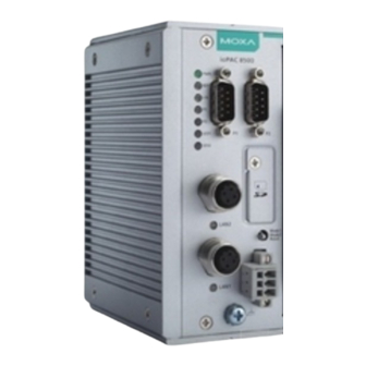
Appearance and Dimensions Appearance ioPAC 8500 Modular Head The following figures depict ioPAC 8500 modular heads. There are two types of modular heads, both have dual Ethernet ports but one is RJ45 and the other is M12. Dimensions ioPAC 8500-2... - Page 19 8500 Hardware ioPAC 8500 Hardware Introduction ioPAC 8500-5 Unit: mm (inch) ioPAC 8500-9 Unit: mm (inch)
-
Page 20: Hardware Block Diagrams
8500 Hardware ioPAC 8500 Hardware Introduction Hardware Block Diagrams ioPAC 8500 CPU Board Block Diagram... -
Page 21: Product Hardware Specifications
8500 Hardware ioPAC 8500 Hardware Introduction Product Hardware Specifications Product Selection Guide Model Name Description ioPAC 8500-2-RJ45-C-T 2 Slot, RJ45, C/C++ ioPAC 8500-5-RJ45-C-T 5 Slot, RJ45, C/C++ ioPAC 8500-9-RJ45-C-T 9 Slot, RJ45, C/C++ ioPAC 8500-2-M12-C-T 2 Slot, M12, C/C++... - Page 22 8500 Hardware ioPAC 8500 Hardware Introduction Power Requirements Power Input: 24 VDC nominal, 9 to 48 VDC Note: Compliant with EN 50155 at 24 VDC Current for I/O Modules: 5 A @ 3.3 VDC (max.) Power Consumption: 3.65 W @ 24 VDC...
-
Page 23: Iopac 8500 Led Indicators
8500 Hardware ioPAC 8500 Hardware Introduction ioPAC 8500 LED Indicators There are 9 LEDs on the ioPAC controller. Category Label Usage System Power On: Power On Off: Power Off System (Kernel) Green: System Ready Ready Green Blinking: System is booting up... -
Page 24: Communication Leds
8500 Hardware ioPAC 8500 Hardware Introduction RDY (Ready LED) The Ready (RDY) LED indicates the status of the system’s kernel. When the LED is green the system kernel is ready. When the LED is green and blinking, the system’s kernel is booting-up. When the Ready (RDY) LED is red, there is either a system error or the system is being reset to factory defaults. -
Page 25: Toggle Switch: Mode 1 And Mode 2
8500 Hardware ioPAC 8500 Hardware Introduction Toggle Switch: Mode 1 and Mode 2 The Mode 1 and Mode 2 toggle switches are user-defined by software (refer to the C/C++ Sample Code Programming Guide for ioPAC RTU Controllers for details). -
Page 26: Module Hardware Introduction
85M Module Hardware Introduction In this chapter, we provide the 85M modules’ specifications. The following topics are covered in this chapter: 85M Module Descriptions Common Specifications Module Specifications 85M-1602-T: Digital Input, 24 VDC, Sink/Source, Dry Contact Type ... -
Page 27: Module Descriptions
4 Serial Ports NOTE Conformal coating available on request. Common Specifications The following is the ioPAC 8500 modules common specification. Environmental Limits Storage Temperature: -40 to 85°C (-40 to 185°F) Ambient Relative Humidity: 5 to 95% (non-condensing) Standards and Certifications... -
Page 28: Module Specifications
8500 Hardware 85M Module Hardware Introduction Module Specifications 85M-1602-T: Digital Input, 24 VDC, Sink/Source, Dry Contact Type The 85M-1602-T modules is a 16-channel, sink/source, or dry contact type digital input module that support wide temperature and high isolation protection. - Page 29 8500 Hardware 85M Module Hardware Introduction Wet Contact (DI to GND): NPN (DI to GND): • On: 0 to 3 VDC • Off: 10 to 30 VDC PNP (DI to GND): • Off: 0 to 3 VDC • On: 10 to 30 VDC...
-
Page 30: 2600-T: Digital Output, 24 Vdc, Sink Type
8500 Hardware 85M Module Hardware Introduction 85M-2600-T: Digital Output, 24 VDC, Sink Type The 85M-2600-T features sink type sixteen digital output channels. The 85M-2600-T can use the module’s digital outputs to determine the state of limit or safety switches, or to receive remote digital signals. - Page 31 8500 Hardware 85M Module Hardware Introduction Operating Temperature: -40 to 75°C Power Requirements Power Consumption: 0.85 W @ 3.3 VDC MTBF (mean time between failure) Time: 792,571 hrs Database: Telcordia (Bellcore) Pin Assignment and Wiring Guide...
-
Page 32: 38Xx-T: Analog Input
8500 Hardware 85M Module Hardware Introduction 85M-38XX-T: Analog Input The 85M-38XX-T series provides eight 16-bit analog input modules. It accepts voltage inputs (0–10 V) and current input (4–20 mA). This high performance analog input module features high density I/O with a flexible topology and hot-swappable functionality. - Page 33 8500 Hardware 85M Module Hardware Introduction Connector: Spring type terminal block Environmental Limits Operating Temperature: -40 to 75°C Power Requirements Power Consumption: 1.05 W @ 3.3 VDC MTBF (mean time between failure) Time: 1,512,906 hrs Database: Telcordia (Bellcore) 85M-3801-T: 8 analog inputs, 4 to 20 mA, 40 kHz...
- Page 34 8500 Hardware 85M Module Hardware Introduction Physical Characteristics Wiring: I/O cable, max. 16 AWG Connector: Spring type terminal block Environmental Limits Operating Temperature: -40 to 75°C Power Requirements Power Consumption: 1.04 W @ 3.3 VDC MTBF (mean time between failure)
- Page 35 8500 Hardware 85M Module Hardware Introduction Pin Assignment and Wiring Guide The following is the 85M-38XX-T module’s pin assignment and wiring guide. Analog Input Data Format The I/O analog inputs have a 16-bit, unipolar, and analog to digital (A/D) converter that measures input voltages from 0–10 V and current from 4–20 mA (with Burnout).
- Page 36 8500 Hardware 85M Module Hardware Introduction The 4–20 mA burnout mode values are defined in the following diagram: Users can define burnout values (BO, default: 2 mA) for selected ranges. When input values are in the burnout range, raw data will register as 0000h to indicate analog input burnout. The definition of raw data is as follows: Burnout Value (BO) 0.0 <...
-
Page 37: 5401-T: Serial Ports
8500 Hardware 85M Module Hardware Introduction 85M-5401-T: Serial Ports The 85M-5401-T module is a 3-in-1 DB44 serial communication port module, which supports RS-232, RS-422, and RS485 communications. The following table shows the serial and protocol communication parameters supported by the 85M-5401-T. - Page 38 8500 Hardware 85M Module Hardware Introduction Data Bits: 7, 8 Stop Bits: 1, 2 Flow Control: RTS/CTS, XON/XOFF Baudrate: 300 bps to 921.6 Kbps Serial Signals RS-232: TxD, RxD, RTS, CTS, DTR, DSR, DCD, GND RS-422: Tx+, Tx-, Rx+, Rx-, GND...
- Page 39 8500 Hardware 85M Module Hardware Introduction DB44 Pin Assignment DB44 (Female): RS-232 Signal Signal Signal TxD3 CTS3 DCD3 RxD3 DTR3 RTS3 DSR3 TxD2 CTS2 DCD2 RxD2 DTR2 RTS2 DSR2 TxD1 CTS1 DCD1 RxD1 DTR1 RTS1 DSR1 DCD0 TxD0 CTS0...
- Page 40 8500 Hardware 85M Module Hardware Introduction DB44 (Female): RS-485 (2-wire) Signal Signal Signal Data3+(B) Data3-(A) Data2+(B) Data2-(A) Data1+(B) Data1-(A) Data0+(B) Data0-(A) DB9 Pin Assignment DB9 (Female): RS-232/RS-422/RS-485 RS-232 RS-422/RS-485(4-wire) RS-485 (2-wire) TxD-(A) TxD+(B) RxD+(A) Data+(B) RxD-(B) Data-(A) 4-15...
- Page 41 8500 Hardware 85M Module Hardware Introduction DIP Switch DIP Switch 1K Ohm Pull High Resistor None (default) 1K Ohm Pull Low Resistor None (default) 120 Ohm Terminal Resistor None (default) Reserved Reserved (default) 4-16...
Need help?
Do you have a question about the ioPAC 8500 and is the answer not in the manual?
Questions and answers