
Related Manuals for Moxa Technologies ioPAC 8020


Summary of Contents for Moxa Technologies ioPAC 8020
- Page 1 8020 Modular RTU Controller User’s Manual First Edition, September 2010 www.moxa.com/product © 2010 Moxa Inc. All rights reserved. Reproduction without permission is prohibited.
- Page 2 8020 Modular RTU Controller User’s Manual The software described in this manual is furnished under a license agreement and may be used only in accordance with the terms of that agreement. Copyright Notice Copyright ©2010 Moxa Inc. All rights reserved.
-
Page 3: Table Of Contents
Table of Contents Introduction ............................1-1 ioPAC 8020 Rugged Remote I/O Overview ..................... 1-2 Product Features ..........................1-2 Package Checklist ..........................1-3 Available Products: ..........................1-4 Product Specifications ......................... 1-4 Physical Dimensions ..........................1-6 Hardware Reference ..........................1-7 Initial Setup ............................2-1 System Architecture .......................... - Page 4 Factory Default Settings ........................F-1...
-
Page 5: Introduction
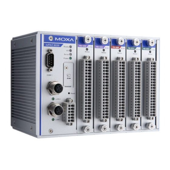
Introduction The ioPAC 8020 modular RTU controller is a rugged, modularized, and flexible I/O combination system. It is designed for harsh environments, such as rolling stock, mining facilities, etc. The hot swappable I/O modules can connect to various sensors and on/off switches for automation applications and the CPU module provides local intelligence that can communicate over Ethernet and IP-based networks. -
Page 6: Product Features
The ioPAC modular RTU controller is an automation system which combines one CPU module with hot swappable I/O modules. This modularity gives the ioPAC 8020 enormous flexibility. The slice type I/O modules that can connect to any combination of sensors and on/off devices, and can transfer the captured data or device status to a host computer via an Ethernet or IP-based networks. -
Page 7: Package Checklist
The ioPAC 8020 controller is an entry level controller with its own private programming language, called Click&Go™. Click&Go has 80 event-based logic rules built-in to give your ioPAC 8020 the intelligence needed to control a wide range of applications. All alarm messages support Unicode text. -
Page 8: Available Products
Introduction Available Products ioPAC 8020-5-M12-T: ioPAC 8020 modular RTU controller with dual M12 Ethernet LAN ports and 5 I/O slots, -40 to 75°C operating temperature ioPAC 8020-5-RJ45-T: ioPAC 8020 modular RTU controller with dual RJ45 Ethernet LAN ports and 5 I/O slots, -40 to 75°C operating temperature... - Page 9 8020 Rugged Remote I/O Introduction Regulatory Approvals EMI: FCC part 15, CISPR (EN55022) Class A EMS: IEC 61000-4-2 (ESD), level 2/3 IEC 61000-4-3 (RS), level 2 IEC 61000-4-4 (EFT), level 2 IEC 61000-4-5 (Surge), level 3 IEC 61000-4-6 (CS), level 2...
-
Page 10: Physical Dimensions
8020 Rugged Remote I/O Introduction Physical Dimensions... -
Page 11: Hardware Reference
8020 Rugged Remote I/O Introduction Hardware Reference Panel Guide NOTE The reset button restarts the server and resets all settings to factory defaults. Use a pointed object such as a straightened paper clip to hold the reset button down for 5 seconds. The READY LED will turn red as you are holding the reset button down. - Page 12 8020 Rugged Remote I/O Introduction LED Indicators for I/O Modules Each DIO or AIO module is equipped with a Module Status LED indicating operation status. LED Name LED Color LED Function Status Not powered or Unknown Module Green Steady On: System ready.
-
Page 13: Initial Setup
Initial Setup This chapter includes information about installing the ioPAC 8020 and its I/O Modules. The following topics are covered in this chapter: Installing the ioPAC on a DIN-Rail Removing the ioPAC from the DIN-Rail Grounding the ioPAC System ... -
Page 14: System Architecture
Modbus Addresses for each I/O channel are fixed by the ioPAC 8020. The ioPAC 8020 uses 24 VDC power inputs. One power input is required, and a second one can be used as a backup power input. The ioPAC 8020 provides 5 VDC power to all connected I/O modules. When the total current consumption of the I/O modules exceeds 1.5A, you will need to insert an extra power module. -
Page 15: Removing The Iopac From The Din-Rail
The ground nut is located on the right side of the ioPAC 8020. Inserting/Removing I/O Modules from the ioPAC The ioPAC 8020 comes with flexible, hot swappable I/O modules. It is easy to manually tighten and loosen the screws. -
Page 16: Connecting The Power System
Step1. Pick one of the two LAN ports and connect the ioPAC 8020 to the host PC with an Ethernet cable. It doesn’t matter which port you use. For initial setup of the ioPAC 8020, we assume that the ioPAC 8020 is... - Page 17 255.255.255.0 None There are two ways to configure the ioPAC 8020. One is to use Modular_ioAdmin, the other is to use the web console. Once the ioPAC 8020 has been detected, modify the settings as needed for your network environment, then restart the I/O.
-
Page 18: Utilities
Utilities This chapter introduces software utilities you can use when configuring the ioPAC modular RTU controller system. These software utilities include: • Modular_ioAdmin: The main utility which allows you to configure, monitor, and edit Click&Go™. • TFTP: The utility which allows you to mass deploy the configuration file. The following topics are covered in this chapter: ... -
Page 19: Introduction To Modular_Ioadmin
Modular_ioAdmin allows the import/export of configuration files and device management lists Modular_ ioAdmin allows the entire configuration of the ioPAC 8020 system to be saved as a file. The file is viewable as text and can serve as a record or backup of the configuration, or as a template. The file includes file title, date, time, model information, and Click&Go™... - Page 20 If two or more I/O systems with the same IP address are found, Modular_ioAdmin will ask you to modify the IP address in a pop up window, and then reboot the I/O system. If multiple ioPAC 8020 units are installed on the same network, remember that each unit has the same default IP address.
- Page 21 Check the Ethernet cable if the methods above do not solve the problem. Login as Administrator After the ioPAC 8020 is displayed in the main window, select the “Device Settings” Tab. Type in the password and then click the “login” button in order to...
- Page 22 If you are installing for the first time, you may see the Module Order Error window. This is because the first time the system starts successfully, the ioPAC 8020 will store the current module combination and all their settings. If the module combination changes, the ioPAC 8020 will detect this unmatched module configuration...
-
Page 23: Modular Ioadmin Main Screen
I/O Configuration tab as illustrated below. The picture displays a figure of the ioPAC 8020 with an empty module below it. The other tabs in the main window take you to Device Information and settings, and further functions are available when you log in as an administrator. Note that configuration options are not available until you log in as an administrator. - Page 24 Several operations are possible from the System menu. Auto Scan Devices will search for ioPAC 8020 devices on the network. When connecting for the first time or recovering from a network disconnection, you can use this command to find I/O systems that are on the network.
- Page 25 Export Modbus Map (Administrator Mode Required) Use this command to export the Modbus Map of the ioPAC 8020 system to a .CSV file. You will need to log in as an administrator to use this function. It is strongly recommended you use this method to record your...
- Page 26 Sort by location Main Window (General) I/O Configuration Tab (General) The I/O Configuration tab shows a picture of an ioPAC 8020 when you are not logged in. This is the default tab when you first open Modular_ioAdmin. Device Info Tab Device information, such as firmware revision, is displayed on the device info tab.
- Page 27 When making configuration changes, you will need to click on Update or on Apply to save the changes. Some changes will require a restart of the ioPAC 8020 system in order to take effect, and you will be given the option to restart the computer if necessary.
- Page 28 8020 Rugged Remote I/O Utilities I/O Status This tab displays the channel values and channel names. It also allows you to assign the alias name to the channel and ON or OFF status. You can drag the border to enlarge or reduce the column width.
- Page 29 There are two situations that will cause the ioPAC modular RTU controller to enter Safe Status. One is if the Host connection is lost, the other is if the internal I/O bus fails. When the ioPAC 8020 is in safe mode, the user can not start Click&Go logic and the user can not change the module configuration.
- Page 30 The Network tab is where you configure IP settings, Modbus/TCP Alive Check Timeout settings, DNS settings, and Web Access settings for the ioPAC 8020. IP Settings: You can set up a static or dynamic IP address for both of the ioPAC 8020 LAN ports, as well as the subnet mask and gateway address.
-
Page 31: Watchdog Tab (Administrator)
Watchdog Tab (Administrator) Click the Watchdog tab to configure the conditions for entering Safe Mode. While the ioPAC 8020 is in Safe Mode, it will stop Click&Go and force each output channel to keep its predefined Safe Status setting. Once the system enters Safe Mode, the LED indicator will blink red and green. -
Page 32: Click&Go Logic Tab (Administrator)
The Click&Go Logic tab is where administrators set up the ioPAC 8020’s active I/O messaging program. Instead of the server reacting passively to repeated polling requests from a host for I/O data, the ioPAC 8020 is able to actively send I/O information to the host when an I/O channel satisfies conditions that you specify. Moxa developed Click&Go logic to provide a powerful and easy-to-use tool for defining the conditions under which I/O... - Page 33 8020 Rugged Remote I/O Utilities You must use “ik8020.txt” as the destination filename when copying a configuration file to the ioPAC 8020 unit. Otherwise, you will receive an error message as shown below: You can use TFTP in a batch file to transfer configuration files for different units. For example, you might have two configuration files that need to be copied to two different servers: ik8020_1.txt for 192.168.127.253, and...
-
Page 34: Using The Built-In Web Console
Using the Built-in Web Console This chapter introduces built-in web console when monitoring the ioPAC modular RTU controller system. The following topics are covered in this chapter: Entering the Web Console Overview Basic Settings Network Settings... -
Page 35: Overview For Iopac 8020
The ioPAC modular RTU controller web console is a browser-based configuration utility which is built into the ioPAC 8020. When the ioPAC modular RTU controller is connected to your network, you may enter the I/O’s IP address in your web browser to access the web console. Note that although most configuration options are available in the web console, some settings are only available through Modular_ioAdmin. -
Page 36: Overview
Press “F5” to refresh the page and update the I/O status. Basic Settings On the Basic Settings page, you may set the ioPAC 8020’s system time or provide the IP address of a time server for time synchronization. - Page 37 8020 will enter Safe Status after there is disruption in communication that exceeds the time specified. Ethernet Configuration On the Ethernet Configuration page, you may set up a static or dynamic IP address for the ioPAC 8020 I/O system, as well as the subnet mask and gateway address.
- Page 38 192.168.1.128 / 255.255.255.128 SNMP Agent On the SNMP Agent page, you may enable SNMP and set the read and write community strings. The ioPAC 8020 provides SNMP v1/v2c/v3 (Simple Network Management Protocol) to allow monitoring of network and I/O devices with SNMP Network Management software.
- Page 39 On the Firmware Update page, you may load new or updated firmware onto the ioPAC 8020. Import System Config On the Import System Config page, you may import a configuration onto the ioPAC 8020 system. The configuration file can be generated by ioAdmin or through the web console. This function can be used to duplicate settings between ioPAC 8020 systems.
- Page 40 New password and Confirm password fields blank. ATTENTION If you forget the password, the ONLY way to configure the ioPAC 8020 is by using the reset button to load the factory defaults. Before you set a password for the first time, it is a good idea to export the configuration to a file when you have finished setting up your ioPAC 8020.
-
Page 41: Click&Go Introduction
Click&Go Introduction Click&Go Logic was developed by Moxa to provide an easy way to program your ioPAC 8020 for active I/O messaging. In the chapter, we will show you how Click&Go Logic works and how to use it to develop your active I/O messaging program. -
Page 42: Overview
24 rules. Supported actions include sending SNMP traps or TCP/UDP messages to up to 10 hosts at a time. Click&Go can also be used to map an input channel on one Moxa ioPAC 8020 to an output channel on another ioPAC 8020 for peer-to-peer I/O communication. -
Page 43: Features
Remote Control and Control by Remote Click&Go is capable of accepting control commands from a remote host or an ioPAC 8020. In addition, it can send out commands to remotely control another ioPAC 8020. Time-stamped Active Messaging All alarms, messages, e-mail notices, and TCP, UDP, and SNMP traps are time-stamped with the exact time of the events. -
Page 44: Working With Rules
Click&Go Introduction Working with Rules Rules are the building blocks of your ioPAC 8020 system. With rules, you define the exact trigger conditions for transmission of I/O information as well as the content and destination of that information. Output channel operation can also be automated based on input channel trigger conditions. -
Page 45: Define Global Variables
8020 Rugged Remote I/O Click&Go Introduction Define Global Work with Configuration Variables Logic Import/Export Activate Configuration Rule-set Define Global Variables Global Variables include the settings of Internal Register Settings, Timer Settings, SNMP Trap Server, E-Mail Server, and Active Message Server. If these functions are going to be used in the Click&Go rule-set, default configuration must first be set in the Global Variable Menu Bar. -
Page 46: Timer Settings
The ioPAC modular RTU controller provides SNMP v2 (Simple Network Management Protocol) to allow monitoring of the network and I/O devices with SNMP Network Management software. It is useful for building automation and telecom applications. When the system information of an ioPAC 8020 needs to be monitored,... -
Page 47: E-Mail Server
8020 Rugged Remote I/O Click&Go Introduction or a Click&Go logic is defined to update the I/O status via SNMP traps, one or up to 10 SNMP trap servers must be defined here. E-Mail Server The E-mail Server configures the parameters of the target e-mail servers and the recipient e-mail addresses. -
Page 48: Active Message Server
Message Recipient List. IF/THEN/ELSE Statement Rules are the building blocks of your ioPAC 8020 system. With rules, you define the exact trigger conditions for transmission of I/O information as well as the content and destination of that information. -
Page 49: If Conditions
8020 Rugged Remote I/O Click&Go Introduction Click&Go Logic can be defined with the following manner: “A” THEN “B”, ELSE “C” For one control logic rule, there are three “A’s” that can be configured. “A” refers to the IF conditions that trigger an action. -
Page 50: Then/Else Actions
Host Connection Fail The Host Connection Fail function refers to when an ioPAC 8020 detects the timeout from a remote Modbus/TCP host and directs it to one of the IF condition of the Click&Go logic. Timeout can be used to trigger an action such as resetting the attached power line on a DO or relay channel to reboot the device. - Page 51 8020 Rugged Remote I/O Click&Go Introduction Internal Register The Internal Register represents a status flag to link the status of the first logic to the second one by specifying other actions in the THEN/ELSE fields. Value from 0 to 255 can be configured here. Select the THEN/ELSE action to Timer and click on the property button to enter the Internal Register Settings window.
-
Page 52: Working With Click&Go Rulesets
In the Click&Go tab, the rules that are displayed in the Click&Go Logic tab comprise the current rule-set, which acts as the brain of your ioPAC 8020 system. The rule-set must be activated for the ioPAC 8020 to commence local control operation as follows: 1. - Page 53 When the rule-set has been activated, it will remain active even when the ioPAC 8020 is disconnected from the host computer or from the network. If the ioPAC 8020 is turned off, ioPAC 8020 operation will resume when it is turned back on. This allows you to use the ioPAC 8020 for PC-independent automation.
-
Page 54: Hot-Swappable I/O Function
Hot-swappable I/O Function The ioPAC 8020 supports hot-swappable I/O. This chapter describes how it works. The following topics are covered in this chapter: Hot-swappable I/O Function Handling unmatched module combination event Turn Off the Module Order Check:... - Page 55 Once the system starts successfully, ioPAC 8020 memorizes the current module combination and all their settings. If you change the module combination, at the next start-up, the ioPAC 8020 will detect an unmatched module combination event and display a warning window. There are two options you can choose to handle the...
- Page 56 8020 Rugged Remote I/O Hot-swappable I/O Function 1. Continue and apply all new modules This action does not clear Click&Go settings. Click&Go will continue or stop operating based on whether or not the “Unmatched I/O Modules” option on the Watchdog tab is checked. You should understand that there is some risk to running Click&Go with the watchdog disabled.
- Page 57 Module Specifications and Wiring 16-channel 24 VDC Digital Input Module RM-1602-T: 16 digital inputs, 24 VDC, sink/source type Inputs per Module: 16 channels, sink/source type On-state Voltage: 24 VDC nominal, 10 VDC min. OFF-state Voltage: 0 to 3 VDC, 3 VDC max. Input Impedance: 3K ohms (typical) Common Type: 16 channels / 2 DI_COMs Response Time: 100 ms...
-
Page 58: Modules Specifications And Wiring
8020 Rugged Remote I/O Modules Specifications and Wiring 16-channel Digital Output Module RM-2600-T: 16 digital outputs, 24 VDC, sink type, 0.2 A Outputs er Module: 16 channels, 24 VDC, sink type Output Impedance: 120m ohms (typical) Off-state Resistance: 500K ohms (typical) - Page 59 8020 Rugged Remote I/O Modules Specifications and Wiring 8-channel Analog Input Module, 16-bit Resolution M-3810-T: 8 analog inputs, 0 to 10 V, 16 bits Inputs per Module: 8 channels, differential Input Current Range: 0 to 10 VDC Input Impendence: > 10M ohms Resolution Range: 16 bits, 0.15 μA/bit...
-
Page 60: Using Modbus/Tcp
Table 5-1 Modbus Function Code Modbus Function Code Introductions Function Code 01 Function code 01 is used to read the discrete output’s ON/OFF status of ioPAC 8020 modules in a binary data format. Request message format for function code 01:... - Page 61 In the response the status of coils 1 to 8 is shown as the byte value 42 hex, equal to 0100 0010 binary. Function Code 02 Function code 02 is used to read the discrete ioPAC 8020 input’s ON/OFF status in a binary data format. Request message format for function code 02:...
- Page 62 Byte Byte Example: Request to force a series of 10 coils starting at address 00017 (11 hex) in ioPAC 8020 module. 01 0F 00 11 00 0A 02 CD 01 The query data contents are two bytes: CD 01 hex, equal to 1100 1101 0000 0001 binary. The binary bits are mapped to the addresses in the following way.
- Page 63 8020 Rugged Remote I/O Using Modbus/TCP Address (000XX): 24 23 22 21 20 19 18 17 - - - - - - 26 25 Response message format for function code 08: The normal responses return the station address, function code, start address, and requested number of coil forced.
-
Page 64: Modbus/Tcp Address Mappings
Modbus/TCP Address Mappings The ioPAC 8020 Modbus Map has three categories: 1. IO image map 2. Module configuration map 3. System configuration map The address arrangement is as below: Map Categories Slot-0 Slot-1 Slot-2 Slot-3 Slot-4 System Configuration Map Base Address: 0x6000... - Page 65 Modbus/TCP Address Mappings How to use: The ioPAC 8020 Modbus addressing is fixed mode; every module occupies 512(0x200) address space. This means that each slot has its own address space of 512. The base address begins at 0x0000. Slot No.
-
Page 66: System Configuration Map (Input Register Map
Modbus/TCP Address Mappings System Configuration Map (Input register map) Using System Configuration Map, users can read the ioPAC system information. The ioPAC 8020 Modbus addressing is fixed mode; every module occupies 512(0x200) of address space. That means that each slot has its own address space of 512. - Page 67 8020 Rugged Remote I/O Modbus/TCP Address Mappings 0x001C 10 Word IP filter enable list 0x0026 20 Word IP filter IP list 0x003A 20 Word IP filter mask list 0x004E 20 Word Time server 0x0062 20 Word Log server 0x0076...
- Page 68 8020 Rugged Remote I/O Modbus/TCP Address Mappings 0x0000~N-1 1 bit Safe mode action (0:fault value, 1:hold last state) N~2N-1 1 bit Fault value 2N~3N-1 1 bit Power-on status For 16Channel Digital Input Module (RM-1600-T): Input register map(R) Address offset...
- Page 69 8020 Rugged Remote I/O Modbus/TCP Address Mappings...
-
Page 70: Used Network Port Numbers
Used Network Port Numbers ioPAC 8020 Network Port Usage Port Type Usage Web Server Modbus Communication SNMP BOOTPC DHCP 4800 Auto search(handled by MOS) -
Page 71: Snmp Mib File
SNMP MIB file The ioPAC 8020 has built-in SNMP(Simple Network Management Protocol) agent software that supports SNMP traps, RFC1317 RS232-like groups, and RFC 1213 MIB-II. The following table lists the standard MIB-II groups, as well as the variable implementation for the ioPAC 8020. - Page 72 8020 Rugged Remote I/O SNMP MIB file numberOfChannels3 numberOfChannels4 systemLiveTime di3Index di4Index firmwareVersion di3Status di4Status do3Index do4Index do3Status do4Status ai3Index ai4Index ai3Type ai4Type ai3Value ai4Value ao3Index ao4Index ao3Range ao4Range ao3Value ao4Value rtd3Index rtd4Index rtd3Enable rtd4Enable rtd3Type rtd4Type rtd3UnitType rtd4UnitType...
- Page 73 Factory Default Settings ioPAC 8020 is configured with the following default private IP address: Default LAN0 IP address: 192.168.127.254 Default LAN0 Netmask: 255.255.255.0 Default LAN0 Gateway: 0.0.0.0(None) Time Zone Communication watchdog: Disable Modbus Idle Timeout: 60 secs Click&Go Power-On Status:...
Need help?
Do you have a question about the ioPAC 8020 and is the answer not in the manual?
Questions and answers